LIGHTING (EXT) HEADLIGHT ASSEMBLY(for LED Headlight) ADJUSTMENT
CAUTION / NOTICE / HINT
- HINT:
- ·
Use the same procedure for RHD and LHD vehicles.
·The procedure listed below is for LHD vehicles.
·Use the same procedure for the RH and LH sides.
·The procedure listed below is for the LH side.
·If it is not possible to correctly adjust the headlight aim, check the headlight assembly and No. 1 headlight bulb installation.
PROCEDURE

 1.PREPARE VEHICLE FOR HEADLIGHT AIMING ADJUSTMENT
Prepare the vehicle:
Make sure that there is no damage to the body around the headlights.
Fill the fuel tank.
Make sure that the oil is filled to the specified level.
Make sure that the coolant is filled to the specified level.
Inflate the tires to the appropriate pressure.
Unload the trunk and vehicle, ensuring that the spare tire, tools and jack are in their original positions.
Have a person of average weight (75 kg, 165 lb) sit in the driver seat.
w/ Headlight Leveling:
Vehicles with manually adjustable headlights should be adjusted to "0".
2. PREPARE FOR HEADLIGHT AIMING (Using a Headlight Aim Tester)
Adjust the headlight aim in accordance with the headlight aim tester instructions.
3.PREPARE FOR HEADLIGHT AIMING
Prepare the vehicle.
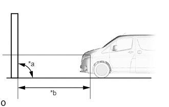
| *a | 90° |
| *b | 25 m or 3 m (82 ft. or 9.84 ft.) |
Place the vehicle in a location that is dark enough to clearly observe the cutoff line. The cutoff line is a distinct line, below which light from the headlights can be observed and above which it cannot.
Place the vehicle at a 90° angle to the wall.
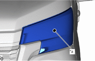
| *a | Center Mark |
Create a 25 m (82 ft.) distance between the vehicle (center marks of the headlight) and the wall.
Make sure that the vehicle is on a level surface.
Position the front wheels straight ahead.
Bounce the vehicle up and down to settle the suspension.
- NOTICE:
-
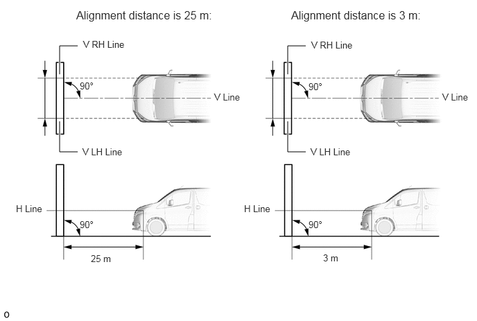
A distance of 25 m (82 ft.) between the vehicle (center marks of the headlights) and the wall is necessary for proper aim adjustment. If unavailable, secure a distance of exactly 3 m (9.84 ft.) for the check and adjustment. (The target zone will change with the distance, so follow the instructions in the illustration.)
Prepare a piece of thick white paper approximately 2 m (6.56 ft.) (height) x 4 m (13.1 ft.) (width) to use as a screen.
Draw a vertical line down the center of the screen (V line).
Set the screen as shown in the illustration.
- HINT:
- ·
Stand the screen perpendicular to the ground.
·Align the V line on the screen with the center of the vehicle.
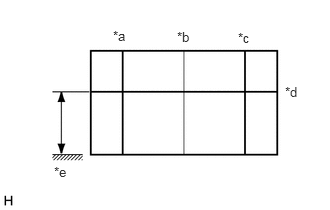
| *a | V LH Line |
| *b | V Line |
| *c | V RH Line |
| *d | H Line |
| *e | Ground |
Draw base lines (H, V LH, and V RH lines) on the screen as shown in the illustration.
- HINT:
- ·
The base lines differ for "low beam inspection" and "high beam inspection".
·Mark the center marks of the low beam headlights on the screen.
H Line (Headlight height):
Draw a horizontal line across the screen so that it passes through the center marks. The H line should be at the same height as the center marks of the headlights.
V LH Line and V RH Line (Center mark position of the left-hand (LH) and right-hand (RH) headlights):
Draw 2 vertical lines so that they intersect the H line at each center mark (aligned with the center marks of the headlight).
4.INSPECT HEADLIGHT AIMING
Cover the headlight on the opposite side to prevent light from the headlight that is not being inspected from affecting the headlight aiming.
- NOTICE:
-
Do not keep the headlight covered for more than 3 minutes. The headlight lens is made of synthetic resin, which may melt or be damaged due to excessive heat.
Start the engine.
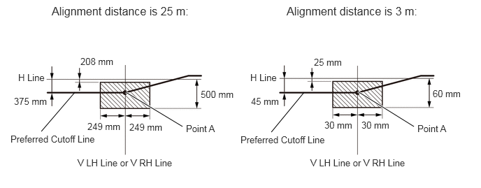
Turn on the headlight and check if the cutoff line matches the preferred cutoff line in the following illustration.
- HINT:
- ·
Since the low beam light and the high beam light are a unit, if the aim on the low beam is correct, the high beam should also be correct. However, check both beams just to make sure.
·The illustration is for LHD vehicles. RHD vehicles are the opposite of the illustration.
·If the alignment distance is 25 m (82 ft.):
The low beam cutoff line should be within 208 mm (8.19 in.) and 500 mm (19.7 in.) below the H line as well as 375 mm (14.8 in.) left or right of the V LH or V RH line.
·If the alignment distance is 3 m (9.84 ft.):
The low beam cutoff line should be within 25 mm (0.984 in.) and 60 mm (2.36 in.) below the H line as well as 45 mm (1.77 in.) left or right of the V LH or V RH line.
·If the alignment distance is 25 m (82 ft.):
The horizontal line of the preferred low beam cutoff line is 249 mm (9.80 in.) below the H line and point A of the preferred low beam cutoff line is on the V LH or V RH line.
·If the alignment distance is 3 m (9.84 ft.):
The horizontal line of the preferred low beam cutoff line is 30 mm (1.18 in.) below the H line and point A of the preferred low beam cutoff line is on the V LH or V RH line.
 1.115,1.375 0.615,1.958 false 2.719,1.885 1.875,1.375 true 4.531,1.375 4.042,1.969 false 6.167,1.885 5.333,1.365 true 4.271,0.063 6.396,0.406 2.125,0.344 12 false Alignment distance is 3 m: 0.771,0.063 2.958,0.406 2.188,0.344 12 false Alignment distance is 25 m: 1.156,2.344 2.656,2.677 1.5,0.333 10 false V LH Line or V RH Line 4.625,2.344 6.125,2.677 1.5,0.333 10 false V LH Line or V RH Line 0.156,1.99 1.531,2.188 1.375,0.198 10 false Preferred Cutoff Line 0.271,1.073 0.74,1.385 0.469,0.313 10 false H Line 3.729,1.073 4.198,1.385 0.469,0.313 10 false H Line 0.208,1.427 0.802,1.76 0.594,0.333 10 false 375 mm 1.198,0.833 1.823,1.167 0.625,0.333 10 false 208 mm 1.302,1.802 1.854,2.135 0.552,0.333 10 false 249 mm 2.99,1.323 3.521,1.656 0.531,0.333 10 false 500 mm 3.74,1.427 4.313,1.76 0.573,0.333 10 false 45 mm 4.677,0.844 5.167,1.177 0.49,0.333 10 false 25 mm 5.385,1.781 5.875,2.115 0.49,0.333 10 false 30 mm 4.833,1.781 5.323,2.115 0.49,0.333 10 false 30 mm 6.448,1.313 6.917,1.646 0.469,0.333 10 false 60 mm 3.583,2 5.042,2.208 1.458,0.208 10 false Preferred Cutoff Line 1.927,1.813 2.479,2.146 0.552,0.333 10 false 249 mm 2.771,1.833 3.302,2.125 0.531,0.292 10 false Point A 6.219,1.833 6.75,2.125 0.531,0.292 10 false Point A
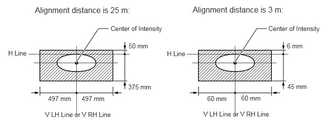
Turn on the high beams and check if the center of intensity for each high beam matches the preferred center of the intensity in the illustration.
- HINT:
- ·
Since the low beam light and the high beam light are a unit, if the aim on the low beam is correct, the high beam should also be correct. However, check both beams just to make sure.
·If the alignment distance is 25 m (82 ft.):
The high beam center of intensity should be within 50 mm (1.97 in.) above and 375 mm (14.8 in.) below the H line as well as 497 mm (1.63 ft.) left or right of the V LH or V RH line.
·If the alignment distance is 3 m (9.84 ft.):
The high beam center of intensity should be within 6 mm (0.236 in.) above and 45 mm (1.77 in.) below the H line as well as 60 mm (2.36 in.) left or right of the V LH or V RH line.
 5.031,1.354 5.51,0.615 5.51,0.615 5.729,0.615 true 1.625,1.354 2.115,0.615 2.115,0.615 2.333,0.615 true 0.75,0.115 2.906,0.448 2.156,0.333 12 false Alignment distance is 25 m: 4.135,0.104 6.292,0.438 2.156,0.333 12 false Alignment distance is 3 m: 4.365,2.375 5.854,2.688 1.49,0.313 10 false V LH Line or V RH Line 0.969,2.385 2.458,2.698 1.49,0.313 10 false V LH Line or V RH Line 5.76,0.531 7.052,0.927 1.292,0.396 10 false Center of Intensity 2.375,0.531 3.667,0.927 1.292,0.396 10 false Center of Intensity 3.583,1.073 4.063,1.417 0.479,0.344 10 false H Line 0.177,1.063 0.656,1.406 0.479,0.344 10 false H Line 1.75,2.042 2.344,2.302 0.594,0.26 10 false 497 mm 1.031,2.042 1.625,2.302 0.594,0.26 10 false 497 mm 2.75,1.792 3.344,2.052 0.594,0.26 10 false 375 mm 2.76,0.906 3.354,1.167 0.594,0.26 10 false 50 mm 4.448,2.042 5.042,2.302 0.594,0.26 10 false 60 mm 5.177,2.031 5.771,2.292 0.594,0.26 10 false 60 mm 6.167,1.781 6.76,2.042 0.594,0.26 10 false 45 mm 6.156,0.906 6.75,1.167 0.594,0.26 10 false 6 mm
5.ADJUST HEADLIGHT AIMING
Adjust the aim vertically and horizontally:
Adjust the aim of each headlight so that it is within the specified range by turning each aiming screw with a screwdriver.
- NOTICE:
-
The final turn of the aiming screw should be made in the clockwise direction. If the screw is tightened excessively, loosen it, and then retighten it so that the final turn of the screw is in the clockwise direction.
- HINT:
- ·
The low beam and high beam headlights are a unit. Adjusting the aim on the low beam to the correct position should also result in the high beam adjustment being correct.
·If it is not possible to correctly adjust the headlight aim, check the headlight assembly and No. 1 headlight bulb installation.
·for LH Side:
The headlight aim moves up when turning the vertical aiming screw clockwise, and moves down when turning the vertical aiming screw counterclockwise. The headlight aim moves right when turning the horizontal aiming screw counterclockwise, and moves left when turning the horizontal aiming screw clockwise.
·for RH Side:
The headlight aim moves up when turning the vertical aiming screw clockwise, and moves down when turning the vertical aiming screw counterclockwise. The headlight aim moves right when turning the horizontal aiming screw clockwise, and moves left when turning the horizontal aiming screw counterclockwise.
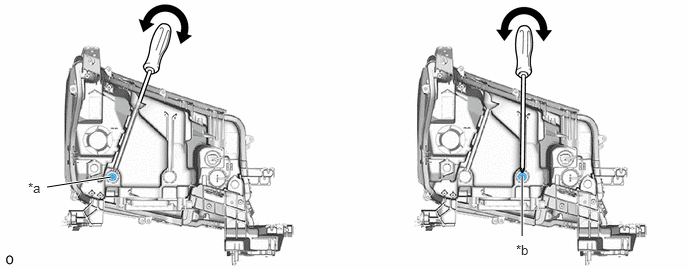
| *a | Horizontal Aiming Screw | *b | Vertical Aiming Screw |

|
Turn in this Direction | - | - |