AC60E AUTOMATIC TRANSMISSION / TRANSAXLE SHIFT LEVER INSPECTION
CAUTION / NOTICE / HINT
- HINT:
- ·
Use the same procedure for RHD and LHD vehicles.
·The procedure listed below is for LHD vehicles.
PROCEDURE

 33560
1.INSPECT SHIFT LOCK CONTROL UNIT ASSEMBLY (w/ Smart Entry and Start System)
33560
1.INSPECT SHIFT LOCK CONTROL UNIT ASSEMBLY (w/ Smart Entry and Start System)
- HINT:
-
If the results of the following inspections are as specified but a malfunction has occurred, replace the shift lock control unit assembly.
Inspect wire harness
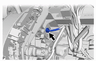
Disconnect the shift lock control ECU connector from the shift lock control unit assembly.
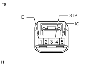
| *a | Front view of wire harness connector
(Shift Lock Control Unit Assembly) |
Measure the voltage according to the value(s) in the table below.
- Standard Voltage:
Tester Connection Condition Specified Condition 4 (STP) - Body ground Brake pedal depressed 11 to 14 V Brake pedal released Below 1 V 5 (IG) - Body ground Ignition switch ON 11 to 14 V Ignition switch off Below 1 V
If the result is not as specified, repair or replace the shift lock control ECU wire harness.
Measure the resistance according to the value(s) in the table below.
- Standard Resistance:
Tester Connection Condition Specified Condition 1 (E) - Body ground Always Below 1 Ω
If the result is not as specified, repair or replace the shift lock control ECU wire harness.
Inspect shift lock solenoid:
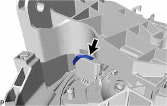
Disconnect the shift lock solenoid connector from the shift lock control ECU.
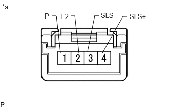
| *a | Front view of wire harness connector
(to Shift Lock Solenoid) |
Measure the resistance according to the value(s) in the table below.
- Standard Resistance:
Tester Connection Condition Specified Condition 1 (P) - 2 (E2) Shift lever in P 10 kΩ or higher Shift lever not in P Below 1 Ω 4 (SLS+) - 3 (SLS-) Always 112 Ω
If the result is not as specified, replace the shift lock control unit assembly.
If the shift lock does not operate when the power source of the shift lock control unit assembly is normal and the resistance between the body ground and the shift lock solenoid is as specified, replace the shift lock control unit assembly.
33560
2.INSPECT SHIFT LOCK CONTROL UNIT ASSEMBLY (w/o Smart Entry and Start System)
- HINT:
-
If the results of the following inspections are as specified but a malfunction has occurred, replace the shift lock control unit assembly.
Inspect wire harness
Disconnect the shift lock control ECU connector from the shift lock control unit assembly.
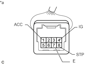
| *a | Front view of wire harness connector
(Shift Lock Control Unit Assembly) |
Measure the voltage according to the value(s) in the table below.
- Standard Voltage:
Tester Connection Condition Specified Condition 8 (STP) - Body ground Brake pedal depressed 11 to 14 V Brake pedal released Below 1 V 1 (ACC) - Body ground Ignition switch ACC 11 to 14 V Ignition switch off Below 1 V 4 (IG) - Body ground Ignition switch ON 11 to 14 V Ignition switch off Below 1 V
If the result is not as specified, repair or replace the shift lock control ECU wire harness.
Measure the resistance according to the value(s) in the table below.
- Standard Resistance:
Tester Connection Condition Specified Condition 7 (E) - Body ground Always Below 1 Ω
If the result is not as specified, repair or replace the shift lock control ECU wire harness.
Inspect the key interlock solenoid operation signal.
Connect the shift lock control ECU connector to the shift lock control unit assembly.
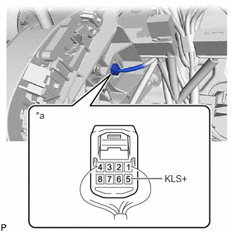
| *a | Component with harness connected
(Shift Lock Control Unit Assembly) |
Measure the voltage according to the value(s) in the table below.
- Standard Voltage:
Tester Connection Condition Specified Condition 5 (KLS+) - Body ground Ignition switch ACC and shift lever in P Below 1 V Ignition switch ACC and shift lever not in P 11 to 14 V
If the result is not as specified, replace the shift lock control unit assembly.
- HINT:
-
Do not disconnect the shift lock control ECU connector.
Inspect shift lock solenoid.
Disconnect the shift lock solenoid connector from the shift lock control ECU.
| *a | Front view of wire harness connector
(to Shift Lock Solenoid) |
Measure the resistance according to the value(s) in the table below.
- Standard Resistance:
Tester Connection Condition Specified Condition 1 (P) - 2 (E2) Shift lever in P 10 kΩ or higher Shift lever not in P Below 1 Ω 4 (SLS+) - 3 (SLS-) Always 112 Ω
If the result is not as specified, replace the shift lock control unit assembly.
If the shift lock does not operate when the power source of the shift lock control unit assembly is normal and the resistance between the body ground and the shift lock solenoid is as specified, replace the shift lock control unit assembly.
3.INSPECT TRANSMISSION CONTROL SWITCH
for LHD:
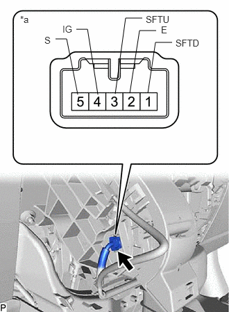
| *a | Component without harness connected
(Transmission Control Switch) |
Disconnect the transmission control switch connector from the shift lock control unit assembly.
Measure the resistance according to the value(s) in the table below.
- Standard Resistance:
Tester Connection Condition Specified Condition 4 (IG) - 5 (S) Shift lever in S, "+" or "-" Below 1 Ω Shift lever not in S, "+" or "-" 10 kΩ or higher 3 (SFTU) - 2 (E) Shift lever held in "+" (Up-shift) Below 1 Ω Shift lever not held in "+" (Up-shift) 10 kΩ or higher 1 (SFTD) - 2 (E) Shift lever held in "-" (Down-shift) Below 1 Ω Shift lever not held in "-" (Down-shift) 10 kΩ or higher
If the result is not as specified, replace the shift lock control unit assembly.
for RHD:
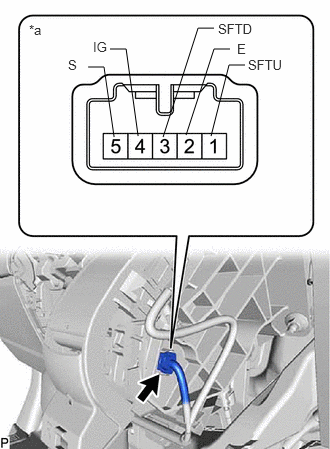
| *a | Component without harness connected
(Transmission Control Switch) |
Disconnect the transmission control switch connector from the shift lock control unit assembly.
Measure the resistance according to the value(s) in the table below.
- Standard Resistance:
Tester Connection Condition Specified Condition 4 (IG) - 5 (S) Shift lever in S, "+" or "-" Below 1 Ω Shift lever not in S, "+" or "-" 10 kΩ or higher 1 (SFTU) - 2 (E) Shift lever held in "+" (Up-shift) Below 1 Ω Shift lever not held in "+" (Up-shift) 10 kΩ or higher 3 (SFTD) - 2 (E) Shift lever held in "-" (Down-shift) Below 1 Ω Shift lever not held in "-" (Down-shift) 10 kΩ or higher
If the result is not as specified, replace the shift lock control unit assembly.