RM35X0E _58 Vehicle Interior _078336 DOOR LOCK _0390094 DOOR LOCK JUNCTION G

DOOR LOCK  DOOR LOCK JUNCTION  INSPECTION  


PROCEDURE

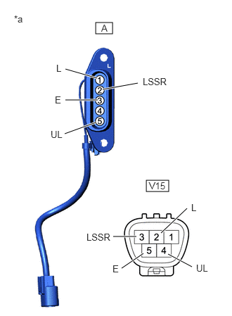
Hide 84261B 1.INSPECT SLIDE DOOR CONTROL JUNCTION MALE (for LH Side)
a.
B540310C01
1.417,0.333 1.667,0.5 0.25,0.167 2.167,2.667 2.5,2.833 0.333,0.167 0.958,1.979 1.417,1.813 true 0.969,1.021 1.438,1.156 true 1.521,1.323 2.042,1.229 true 0.969,1.479 1.448,1.479 true 1.677,3.5 2.021,3.5 true 2.385,3.448 2.771,3.083 true 2.49,3.76 2.844,3.948 true 1.802,3.969 2.125,3.75 true 0.208,0.198 0.521,0.354 0.313,0.156 10 false *a 0.833,0.927 1.146,1.083 0.313,0.156 10 false L 2.115,1.125 2.729,1.385 0.615,0.26 10 false LSSR 0.75,1.906 1.063,2.063 0.313,0.156 10 false UL 0.813,1.396 1.125,1.552 0.313,0.156 10 false E 1.5,0.333 1.656,0.531 0.156,0.198 10 false A 2.208,2.667 2.646,2.865 0.438,0.198 10 false V15 1.281,3.427 1.792,3.615 0.51,0.188 10 false LSSR 2.833,2.99 3.146,3.146 0.313,0.156 10 false L 2.906,3.885 3.219,4.042 0.313,0.156 10 false UL 1.667,3.896 1.979,4.052 0.313,0.156 10 false E
*a Component without harness connected
(Slide door control junction male)


Check the resistance of the slide door control junction male.

i.

Measure the resistance according to the value(s) in the table below.

Standard Resistance:
TYPE A
Tester Connection Condition Specified Condition
A-1 (L) - V15-2 (L) Always Below 1 Ω
A-5 (UL) - V15-4 (UL) Always Below 1 Ω

TYPE B
Tester Connection Condition Specified Condition
A-1 (L) - V15-2 (L) Always Below 1 Ω
A-2 (LSSR) - V15-3 (LSSR) Always Below 1 Ω
A-3 (E) - V15-5 (E) Always Below 1 Ω
A-5 (UL) - V15-4 (UL) Always Below 1 Ω


If the result is not as specified, replace the slide door control junction male.


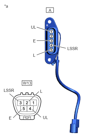
Hide 84261B 2.INSPECT SLIDE DOOR CONTROL JUNCTION MALE (for RH Side)
a.
B540311C01
1.573,0.26 1.823,0.427 0.25,0.167 0.75,2.75 1.083,2.917 0.333,0.167 1.25,1.385 1.688,1.385 true 1.094,3.74 1.396,4 true 1.25,0.927 1.688,1.063 true 1.802,1.542 2.24,1.646 true 1.25,1.875 1.688,1.708 true 0.448,4.021 0.729,3.74 true 0.323,3.198 0.625,3.458 true 0.979,3.458 1.323,3.125 true 0.146,0.125 0.458,0.281 0.313,0.156 10 false *a 1.656,0.271 1.813,0.469 0.156,0.198 10 false A 0.781,2.75 1.26,2.948 0.479,0.198 10 false W13 1.125,1.313 1.281,1.51 0.156,0.198 10 false E 1.052,0.844 1.313,1.042 0.26,0.198 10 false UL 2.292,1.573 2.698,1.771 0.406,0.198 10 false LSSR 1.125,1.802 1.281,2 0.156,0.198 10 false L 1.458,3.927 1.719,4.125 0.26,0.198 10 false UL 0.302,3.948 0.458,4.146 0.156,0.198 10 false E 0.125,3 0.531,3.198 0.406,0.198 10 false LSSR 1.365,3.031 1.521,3.229 0.156,0.198 10 false L
*a Component without harness connected
(Slide door control junction male)


Check the resistance of the slide door control junction male.

i.

Measure the resistance according to the value(s) in the table below.

Standard Resistance:
TYPE A
Tester Connection Condition Specified Condition
A-1 (UL) - W13-4 (UL) Always Below 1 Ω
A-5 (L) - W13-2 (L) Always Below 1 Ω

TYPE B
Tester Connection Condition Specified Condition
A-1 (UL) - W13-4 (UL) Always Below 1 Ω
A-3 (E) - W13-5 (E) Always Below 1 Ω
A-4 (LSSR) - W13-3 (LSSR) Always Below 1 Ω
A-5 (L) - W13-2 (L) Always Below 1 Ω


If the result is not as specified, replace the slide door control junction male.


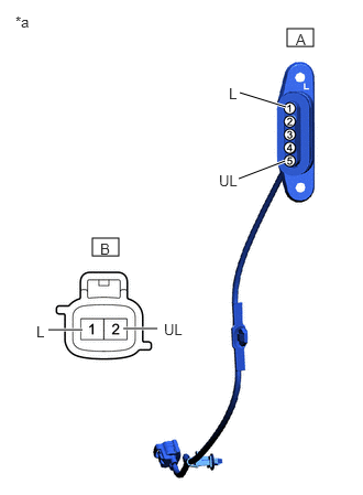
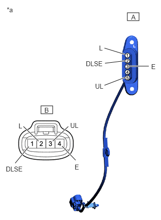
Hide 84262B 3.INSPECT SLIDE DOOR CONTROL JUNCTION FEMALE
a.
B540312C01
2.719,0.271 2.969,0.438 0.25,0.167 0.875,2.25 1.125,2.417 0.25,0.167 2.271,0.875 2.708,1.01 true 2.26,1.688 2.698,1.521 true 0.458,3.115 0.781,3.115 true 1.167,3.104 1.49,3.104 true 0.146,0.125 0.458,0.281 0.313,0.156 10 false *a 2.802,0.292 2.958,0.49 0.156,0.198 10 false A 0.948,2.271 1.104,2.469 0.156,0.198 10 false B 2.073,1.625 2.333,1.823 0.26,0.198 10 false UL 2.167,0.802 2.323,1 0.156,0.198 10 false L 1.552,3.031 1.813,3.229 0.26,0.198 10 false UL 0.344,3.052 0.5,3.25 0.156,0.198 10 false L
*a Component without harness connected
(Slide door control junction female)


Check the resistance of the slide door control junction female (for Type A).

i.

Measure the resistance according to the value(s) in the table below.

Standard Resistance:
Tester Connection Condition Specified Condition
A-1 (L) - B-1 (L) Always Below 1 Ω
A-5 (UL) - B-2 (UL) Always Below 1 Ω


If the result is not as specified, replace the slide door control junction female.


b.
B540313C01
2.719,0.271 2.969,0.438 0.25,0.167 0.875,2.25 1.125,2.417 0.25,0.167 2.229,1.021 2.667,1.156 true 2.229,1.813 2.667,1.646 true 0.323,3.469 0.615,3.115 true 1.323,3.104 1.615,3.406 true 2.75,1.406 3.177,1.406 true 2.24,1.344 2.667,1.292 true 0.5,2.688 0.823,3 true 1.125,3 1.458,2.688 true 0.146,0.125 0.458,0.281 0.313,0.156 10 false *a 2.802,0.281 2.958,0.479 0.156,0.198 10 false A 0.948,2.26 1.104,2.458 0.156,0.198 10 false B 2.031,1.75 2.292,1.948 0.26,0.198 10 false UL 2.115,0.938 2.271,1.135 0.156,0.198 10 false L 1.5,2.583 1.76,2.781 0.26,0.198 10 false UL 0.396,2.594 0.552,2.792 0.156,0.198 10 false L 3.229,1.333 3.385,1.531 0.156,0.198 10 false E 1.833,1.271 2.323,1.49 0.49,0.219 10 false DLSE 0.125,3.51 0.615,3.729 0.49,0.219 10 false DLSE 1.594,3.469 1.75,3.667 0.156,0.198 10 false E
*a Component without harness connected
(Slide door control junction female)


Check the resistance of the slide door control junction female (for Type B).

i.

Measure the resistance according to the value(s) in the table below.

Standard Resistance:
Tester Connection Condition Specified Condition
A-1 (L) - B-2 (L) Always Below 1 Ω
A-2 (DLSE) - B-1 (DLSE) Always Below 1 Ω
A-3 (E) - B-4 (E) Always Below 1 Ω
A-5 (UL) - B-3 (UL) Always Below 1 Ω


If the result is not as specified, replace the slide door control junction female.