POWER ASSIST SYSTEMS VANE PUMP(for 7GR-FKS(w/o Variable Flow Control Solenoid Valve)) REASSEMBLY
CAUTION / NOTICE / HINT
- NOTICE:
- ·
When using a vise, place aluminum plates between the part and vise.
·When using a vise, do not overtighten it.
PROCEDURE

 1.INSTALL VANE PUMP HOUSING OIL SEAL
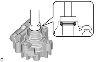
Using SST and a press, press in a new vane pump housing oil seal.
- SST
- 09950-60011 (09951-00280)
09950-70010 (09951-07100)
- NOTICE:
- ·
Make sure to install the vane pump housing oil seal so that it faces the correct direction.
·Be careful not to damage the vane pump housing oil seal.
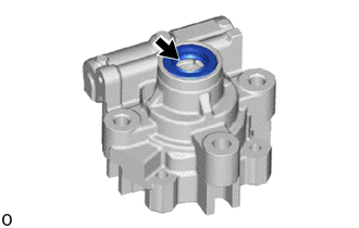

|
MP Grease |
Coat the lip of vane pump housing oil seal with MP grease.
2.INSTALL SHAFT WITH PULLEY
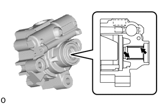
|
|
Power Steering Fluid |
Coat the inside surface of the bushing in the front housing with power steering fluid.
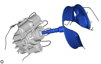
| *a | Protective Tape |
Install the shaft with pulley to the front housing.
- NOTICE:
- ·
Wrap protective tape around the spline of the vane pump shaft with vane pump pulley in order to prevent damage to the oil seal.
·Be careful not to damage the vane pump housing oil seal.
3.INSTALL FRONT VANE PUMP SIDE PLATE
|
|
Power Steering Fluid |
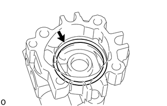
Coat a new O-ring with power steering fluid and install it to the front housing.
|
|
Power Steering Fluid |

|
Install in this Direction |
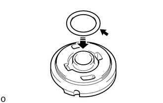
Coat a new O-ring with power steering fluid and install it to the front vane pump side plate.
|
|
Install in this Direction |
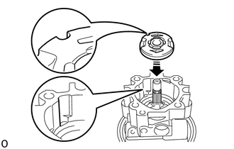
Install the front vane pump side plate to the front housing while aligning the semicircle-shaped cuts of both parts.
- NOTICE:
-
Be sure to install the front vane pump side plate in the correct position and with the correct orientation.
4.INSTALL VANE PUMP CAM RING
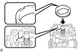
| *a | Inscribed Mark |
With the inscribed mark facing upward, install the vane pump cam ring to the front housing while aligning the semicircle-shaped cuts of both parts.
- NOTICE:
-
Be sure to install the vane pump cam ring in the correct position and with the correct orientation.
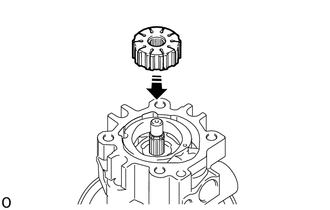
5.INSTALL VANE PUMP ROTOR
|
|
Install in this Direction |
Install the vane pump rotor with the inscribed mark facing outward.
Coat the 10 vane plates with power steering fluid.
| *a | Outward |
| *b | Inward |
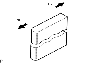
Install the 10 vane pump plates.
- NOTICE:
-
Make sure that the round ends of the vane pump plates are facing outward.
6.INSTALL VANE PUMP SHAFT SNAP RING
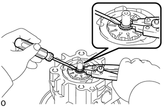
Using a snap ring expander, install a new vane pump shaft snap ring onto the shaft with pulley.
7.INSTALL REAR HOUSING
Coat the vane pump rear housing of the shaft sub-assembly with pulley and the surrounding surface with power steering fluid.
Coat a new O-ring with power steering fluid and install it to the rear housing.
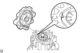
| *a | Align |
Align the straight pin of the rear housing with the dent of the cam ring, side plate and front housing.
- NOTICE:
-
Make sure that the O-ring is not out of position before installing the rear housing.
Install the rear housing with the 4 bolts.
- Torque:
- 22 N*m (224 kgf*cm, 16 ft.*lbf)
8.INSPECT ROTATING TORQUE
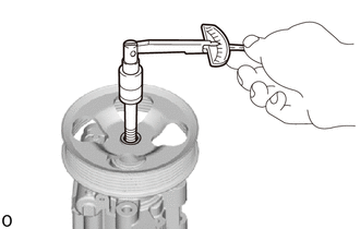
| *a | Service Bolt |
Check that the vane pump assembly rotates smoothly without abnormal noise.
Temporarily install the service bolt.
- Recommended Service Bolt:
Item Specified Condition Thread Diameter 10 mm (0.394 in.) Thread Pitch 1.25 mm (0.0492 in.) Bolt Length 50 mm (1.97 in.)
Using a torque wrench, check the pump rotating torque.
- Standard rotating torque:
0.27 N*m (3 kgf*cm, 2 in.*lbf) or less
If the rotating torque is not as specified, check the installation of the housing oil seal.
9.INSTALL POWER STEERING SUCTION PORT UNION
Coat a new O-ring with power steering fluid, and install it onto the power steering suction port union.
Install the power steering suction port union with the bolt.
- Torque:
- 12 N*m (122 kgf*cm, 9 ft.*lbf)
10.INSTALL FLOW CONTROL VALVE
Coat the flow control valve compression spring and flow control valve with power steering fluid.

| *1 | Flow Control Valve Compression Spring |
| *2 | Flow Control Valve |
| *3 | O-ring |
| *4 | Pressure Port Union |
Install the flow control valve compression spring.
Install the flow control valve so that it faces the correct direction.
Coat a new O-ring with power steering fluid and install it to the pressure port union.
Install the pressure port union.
- Torque:
- 69 N*m (704 kgf*cm, 51 ft.*lbf)