POWER ASSIST SYSTEMS VANE PUMP(for 7GR-FKS(w/o Variable Flow Control Solenoid Valve)) INSPECTION
PROCEDURE

 1.INSPECT CLEARANCE BETWEEN VANE PUMP SHAFT AND BUSHING IN FRONT HOUSING
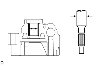
Using a micrometer, measure the diameter (a) of the shaft with pulley.
Using a caliper gauge, measure the inside diameter (b) of the front housing.
- NOTICE:
-
Do not damage the bushing in the front housing.
Subtract (a) from (b) to calculate the oil clearance.
- Maximum clearance:
0.07 mm (0.00276 in.)
If the clearance is more it is more than the maximum, replace the shaft with pulley.
2.INSPECT VANE PUMP ROTOR AND VANE PUMP PLATES CLEARANCE
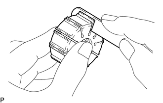
Using a feeler gauge, measure the clearance between the side face of the vane pump rotor groove and the vane pump plates.
- Maximum clearance:
0.025 mm (0.000984 in.)
If the clearance is more than the maximum, replace the vane pump plates, vane pump rotor and vane pump cam ring.
- HINT:
-
Refer to the following table to select an appropriate combination of vane pump rotor, vane pump cam ring and vane pump plates.
- Combination of Vane Pump Rotor, Vane Pump Cam Ring and Vane Pump Plates:
Vane Pump Cam Ring Part No. Vane Pump Rotor Part No. Vane Plate Part No. 44325-60080 44313-60010 44345-60060 44325-60090 44313-60020 44345-60070 44325-60100 44313-60030 44345-60080 44325-60110 44313-60040 44345-60090
3.INSPECT FLOW CONTROL VALVE
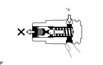
| *a | Compressed Air |

| *a | Mark |
Check the flow control valve for leakage. Close one of the holes and apply compressed air at 392 to 490 kPa (4.00 to 4.99 kgf/cm2, 56.9 to 71.0 psi) to the hole on the opposite side. Confirm that the air does not flow out of the end hole.
- NOTICE:
-
Make sure to use clean and dry air.
If there is leakage, replace the flow control valve.
- HINT:
- ·
Check the mark on the front housing and replace the flow control valve with one having the same mark as that of the front housing.
·Refer to the following table to select an appropriate combination of front housing and flow control valve.
- Combination of Front Housing and Flow Control Valve:
Front Housing Mark Flow Control Valve Mark Flow Control Valve Part No. A 44330-60160 A B 44330-60170 B C 44330-60180 C D 44330-60190 D E 44330-60200 E F 44330-60210 F
Coat the flow control valve with power steering fluid.
- NOTICE:
-
Make sure to use new power steering fluid.
Insert the flow control valve into the flow control valve installation hole of the front housing, and check that the flow control valve enters smoothly under its own weight.
If the flow control valve does not enter the front housing smoothly, replace the flow control valve.
4.INSPECT FLOW CONTROL VALVE COMPRESSION SPRING
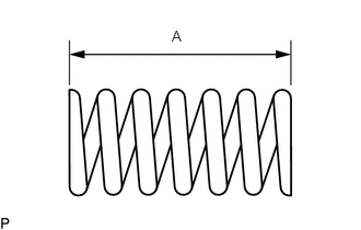
Using a vernier caliper, measure the free length of the flow control valve compression spring.
- Minimum Free Length (A) (Reference):
31.95 mm (1.26 in.)
If the length is less than the minimum, replace the flow control valve compression spring.
5.INSPECT PRESSURE PORT UNION
If the union seat in the pressure port union sub-assembly is severely damaged, replace the pressure port union sub-assembly.