HEATING / AIR CONDITIONING SOLAR SENSOR INSPECTION
PROCEDURE

 88625H
1.INSPECT COOLER THERMISTOR (SOLAR SENSOR)
88625H
1.INSPECT COOLER THERMISTOR (SOLAR SENSOR)
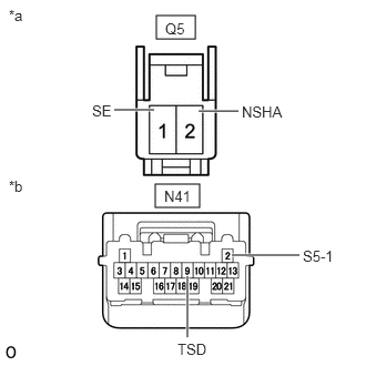
| *a | Front view of wire harness connector
(to Cooler Thermistor (Solar Sensor)) |
| *b | Front view of wire harness connector
(to Air Conditioning Amplifier Assembly) |
Check the wire harness.
Disconnect the N41 air conditioning amplifier assembly connector.
Disconnect the Q5 cooler thermistor (solar sensor) connector.
Measure the resistance according to the value(s) in the table below.
- Standard Resistance:
Tester Connection Condition Specified Condition Q5-1 (SE) - N41-2 (S5-1) Always Below 1 Ω Q5-2 (NSHA) - N41-9 (TSD) Always Below 1 Ω Q5-1 (SE) - Body ground Always 10 kΩ or higher Q5-2 (NSHA) - Body ground Always 10 kΩ or higher
If the resistance is not as specified, repair the wire harness.
Reconnect the N41 air conditioning amplifier assembly connector.
Turn the ignition switch to ON.
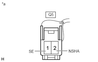
| *a | Front view of wire harness connector
(to Cooler Thermistor (Solar Sensor)) |
Measure the voltage according to the value(s) in the table below.
- Standard Voltage:
Tester Connection Condition Specified Condition Q5-1 (SE) - Q5-2 (NSHA) Ignition switch off Below 1 V Q5-1 (SE) - Q5-2 (NSHA) Ignition switch ON 4.75 to 5.25 V
If the voltage is not as specified, replace the air conditioning amplifier assembly.
Check the cooler thermistor (solar sensor).
Reconnect the connector to the cooler thermistor (solar sensor).
Turn the ignition switch to ON.
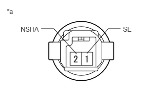
| *a | Component with harness connected
(Cooler Thermistor (Solar Sensor)) |
Measure the voltage according to the value(s) in the table below.
- Standard Voltage:
Tester Connection Condition Specified Condition Q5-1 (SE) - Q5-2 (NSHA) Sensor is subjected to electric light 0.8 to 4.3 V Q5-1 (SE) - Q5-2 (NSHA) Sensor is covered with a cloth Below 0.8 V
- NOTICE:
- ·
The connection procedure for using a digital tester such as a TOYOTA electrical tester is shown above. When using an analog tester, connect the negative (-) lead to terminal 1 and the positive (+) lead to terminal 2 of the cooler thermistor (solar sensor).
·Do not bring the positive and negative tester probes too close to each other as a short circuit may occur.
- HINT:
- ·
Use an incandescent light for inspection. Bring it within about 300 mm (11.8 in.) of the cooler thermistor (solar sensor).
·As the inspection light is moved away from the sensor, the voltage decreases.
·Check from the rear of the connector while it is connected to the cooler thermistor (solar sensor).
If the voltage is not as specified, replace the cooler thermistor (solar sensor).