STEERING GEAR / LINKAGE STEERING GEAR(for LHD) DISASSEMBLY
CAUTION / NOTICE / HINT
- NOTICE:
- ·
When using a vise, place aluminum plates between the part and vise.
·When using a vise, do not overtighten it.
PROCEDURE

 44416
1.REMOVE STEERING GEAR OUTLET RETURN TUBE
44416
1.REMOVE STEERING GEAR OUTLET RETURN TUBE
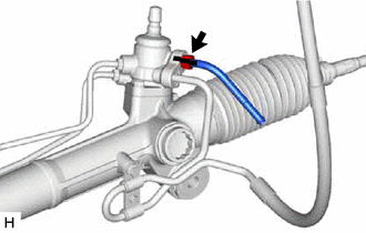
| *a | Matchmark |
Put matchmarks on the steering gear outlet return tube and rack and pinion power steering gear assembly.
Using a union nut wrench, remove the steering gear outlet return tube and O-ring.
44410
2.REMOVE PRESSURE FEED TUBE ASSEMBLY
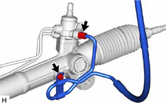
Remove the bolt.
Using a union nut wrench, remove the pressure feed tube and O-ring.
3.REMOVE STEERING TURN PRESSURE TUBE
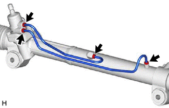
Using a union nut wrench, remove the 2 steering turn pressure tubes.
Remove the 4 O-rings.
4.SECURE RACK AND PINION POWER STEERING GEAR ASSEMBLY
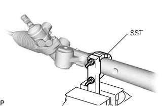
Using SST, secure the rack and pinion power steering gear assembly.
- SST
- 09612-00012
45047
5.REMOVE TIE ROD END SUB-ASSEMBLY LH
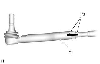
| *1 | Rack End |
| *a | Matchmark |
Put matchmarks on the tie rod end sub-assembly LH, lock nut and rack end.
Loosen the lock nut and remove the tie rod end sub-assembly LH and lock nut.
45046
6.REMOVE TIE ROD END SUB-ASSEMBLY RH
- HINT:
-
Use the same procedure described for the LH side.
7.REMOVE STEERING RACK BOOT CLAMP LH
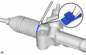
Using a screwdriver, remove the steering rack boot clamp LH.
- NOTICE:
-
Be careful not to damage the steering rack boot LH.
8.REMOVE STEERING RACK BOOT CLAMP RH
- HINT:
-
Use the same procedure described for the LH side.
9.REMOVE STEERING RACK BOOT CLIP LH
Using pliers, remove the steering rack boot clip LH.
- NOTICE:
-
Be careful not to damage the steering rack boot.
10.REMOVE STEERING RACK BOOT CLIP RH
- HINT:
-
Use the same procedure described for the LH side.
11.REMOVE STEERING RACK BOOT LH
Remove the steering rack boot LH.
12.REMOVE STEERING RACK BOOT RH
- HINT:
-
Use the same procedure described for the LH side.
13.REMOVE STEERING RACK END SUB-ASSEMBLY
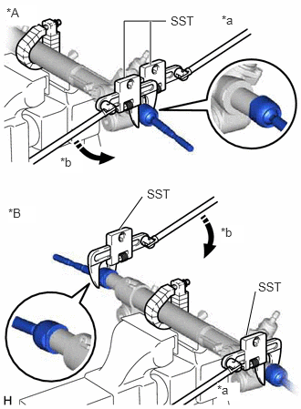
| *A | for LH Side |
| *B | for RH Side |
| *a | Hold |
| *b | Turn |
Using SST, hold the steering rack end sub-assembly.
- SST
- 09922-10010
Using SST, remove the steering rack end (LH side) from the steering rack sub-assembly.
- SST
- 09922-10010
- NOTICE:
-
Rotate SST in the direction shown in the illustration.
Using SST, remove the steering rack end (RH side) from the steering rack sub-assembly.
- SST
- 09922-10010
- NOTICE:
-
Rotate SST in the direction shown in the illustration.