STEERING COLUMN STEERING SYSTEM ADJUSTMENT
PROCEDURE

 1.ADJUST STEERING CENTER
- HINT:
-
This is the adjustment procedure for when the steering is off center.
Check if the steering wheel is off center.
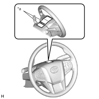
| *a | Masking Tape |
Apply masking tape to the top center of the steering wheel and steering column upper cover.
Drive the vehicle in a straight line for 100 m (328 ft.) at a constant speed of 56 km/h (35 mph), and hold the steering wheel to maintain the course.
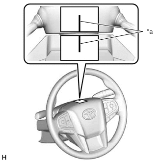
| *a | Marked Line |
Draw a line on the masking tape as shown in the illustration.
Turn the steering wheel to the center position.
- HINT:
-
Look at the upper surface of the steering wheel, steering spoke and SRS airbag line to find the center position.
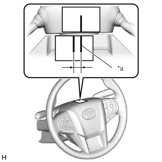
| *a | Marked Line |
Draw a new line on the masking tape on the steering wheel as shown in the illustration.
Measure the distance between the 2 lines on the masking tape on the steering wheel.
Convert the measured distance to steering angle.
- HINT:
- ·
Measured distance of 1 mm (0.0394 in.) = Steering angle of approximately 1 degree.
·Make a note of the steering angle.
Adjust the steering angle.
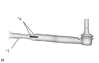
| *1 | Rack End |
| *a | Matchmark |
Draw a line on the RH and LH tie rod ends and rack ends where it can be easily seen.
Measure the distance from the RH and LH tie rod ends to the ends of the rack end screws.
- HINT:
- ·
Measure both the RH and LH sides.
·Make a note of the measured values.
Loosen the RH and LH lock nuts.
Turn the RH and LH rack ends by the same amount (but in different directions) according to the steering angle.
- HINT:
-
One 360 degree turn of the rack ends (1.0 mm (0.0394 in.)) horizontal movement equals 12 degrees of steering angle.
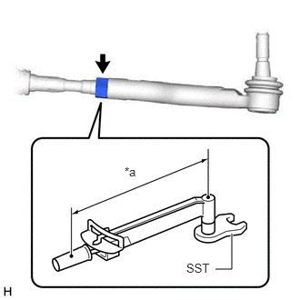
| *a | Torque Wrench Fulcrum Length |
Using SST, tighten the RH and LH lock nuts to the specified torque.
- SST
- 09922-10240
- Torque:
- Specified tightening torque : 62 N*m (632 kgf*cm, 46 ft.*lbf)
- NOTICE:
-
Make sure that the boots are not twisted.
- HINT:
- ·
Calculate the torque wrench reading when changing the fulcrum length of the torque wrench.
·When using SST (fulcrum length of 40 mm (1.575 in.)) + torque wrench (fulcrum length of 380 mm (14.961 in.)): 56.1 N*m (572 kgf*cm, 41 ft.*lbf)