DOOR LOCK SLIDE DOOR LOCK(except Wagon) INSTALLATION
CAUTION / NOTICE / HINT
- HINT:
- ·
Use the same procedure for RHD and LHD vehicles.
·The procedure listed below is for LHD vehicles.
·Use the same procedure for the RH and LH sides.
·Use the same procedure described for the RH side.
PROCEDURE

 69630C
1.INSTALL SLIDE DOOR LOCK REMOTE CONTROL ASSEMBLY RH
69630C
1.INSTALL SLIDE DOOR LOCK REMOTE CONTROL ASSEMBLY RH
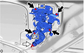
Apply MP grease to the sliding parts of the slide door lock remote control assembly RH.

|
Bolt |

|
Connector |
Attach the guide and install the slide door lock remote control assembly RH with the 4 bolts.
- Torque:
- 7.5 N*m (76 kgf*cm, 66 in.*lbf)
Connect the each connector.
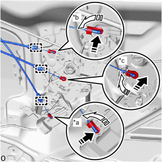
| *a | Locking Cable (Orange) |
| *b | Open Cable (Blue) |
| *c | Close Cable (Purple) |

|
Install in this Direction (1) |

|
Install in this Direction (2) |
Attach the 3 snaps and connect the 3 cables to the slide door lock remote control assembly RH as shown in the illustration.
Attach the clamp.
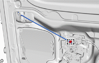
Attach the clamp and install the rear door lock remove control link RH.
69330E
2.INSTALL SLIDE DOOR LOCK ASSEMBLY RH (w/o Power Slide Door)
Apply MP grease to the sliding part of the rear door lock assembly RH.
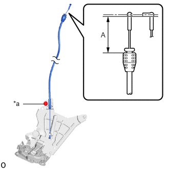
| *a | Adjusting Bolt |
Loosen the adjusting bolt.
Adjust the cable as shown in the illustration.
- OK:
Area Standard Dimension A 37.4 to 39.0 mm (1.472 to 1.535 in.)
Tighten the adjusting bolt.
- Torque:
- 5.5 N*m (56 kgf*cm, 49 in.*lbf)
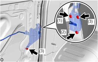
Using a T30 "TORX" socket wrench, install the rear door lock assembly RH with the 4 "TORX" screws.
- Torque:
- 8.0 N*m (82 kgf*cm, 71 in.*lbf)
- HINT:
-
Install the "TORX" screws in the order shown in the illustration.
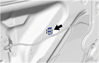
Attach the clamp and install the cable clamp.
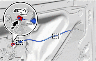
|
|
Install in this Direction (1) |
|
|
Install in this Direction (2) |
Attach the snap as shown in the illustration.
Attach the clamp.
Connect the cable to the cable clamp.
69200
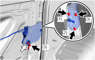
3.INSTALL POWER SLIDE DOOR LOCK ASSEMBLY RH (w/ Power Slide Door)
Apply MP grease to the sliding part of the power slide door lock assembly RH.
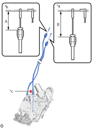
| *a | Lock Cable (Gray) |
| *b | Open Cable |
| *c | Adjusting Bolt |
Loosen the adjusting bolt.
Adjust the cable as shown in the illustration.
- OK:
Area Standard Dimension A 37.3 to 38.9 mm (1.47 to 1.53 in.) B 49.6 to 52.8 mm (1.95 to 2.08 in.)
Tighten the adjusting bolt.
- Torque:
- 5.5 N*m (56 kgf*cm, 49 in.*lbf)
|
|
"TORX" Screw |
|
|
Connector |
Using a T30 "TORX" socket wrench, install the power slide door lock assembly RH with the 4 "TORX" screws.
- Torque:
- 8.0 N*m (82 kgf*cm, 71 in.*lbf)
- HINT:
-
Install the "TORX" screws in the order shown in the illustration.
Connect the connector.
Attach the clamp and install the cable clamp.
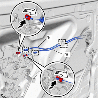
| *a | Lock Cable (Gray) |
| *b | Open Cable |
|
|
Install in this Direction |
Attach the 2 snaps and connect the 2 cables to the slide door lock remote control assembly RH as shown in the illustration.
Attach the clamp.
Connect the 2 cables to the cable clamp.
69370B
4.INSTALL SLIDE DOOR FRONT LOCK ASSEMBLY RH
Apply MP grease to the sliding part of the slide door front lock assembly RH.
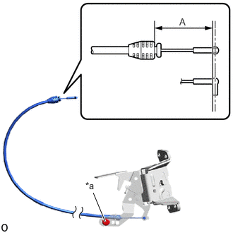
| *a | Adjusting Bolt |
Loosen the adjusting bolt.
Adjust the cable as shown in the illustration.
- OK:
Area Standard Dimension A 29.7 to 31.7 mm (1.17 to 1.25 in.)
Tighten the adjusting bolt.
- Torque:
- 5.4 N*m (55 kgf*cm, 48 in.*lbf)
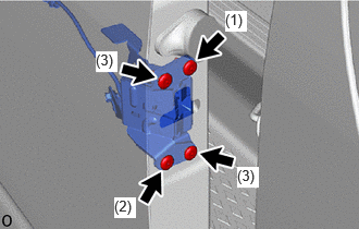
Using a T30 "TORX" socket wrench, install the power slide door lock assembly RH with the 4 "TORX" screws.
- Torque:
- 7.5 N*m (76 kgf*cm, 66 in.*lbf)
- HINT:
-
Install the "TORX" screws in the order shown in the illustration.
|
|
Install in this Direction (1) |
|
|
Install in this Direction (2) |
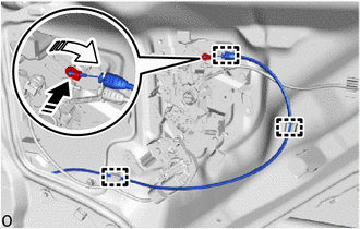
Attach the snap as shown in the illustration.
Attach the clamp.
Connect the cable to the cable clamp.
69730A
5.INSTALL REAR DOOR LOCK CONTROL LINK ASSEMBLY RH (w/ Cover)
|
|
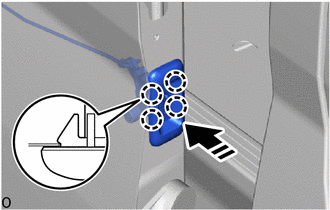
Install in this Direction |
Attach the claw and install the rear door lock control link assembly RH.
|
|
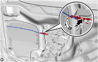
Install in this Direction (1) |
|
|
Install in this Direction (2) |
Attach the snap as shown in the illustration.
67851E
6.INSTALL SLIDE DOOR SERVICE HOLE COVER RH
67603
7.INSTALL REAR DOOR TRIM BOARD SUB-ASSEMBLY RH (for Semi-trim, for Type A)
67603
8.INSTALL REAR DOOR TRIM BOARD SUB-ASSEMBLY RH (for Semi-trim, for Type B)
67680B
9.INSTALL SLIDE DOOR TRIM BOARD ASSEMBLY RH (for Full-trim, for Standard Roof)
67680B
10.INSTALL SLIDE DOOR TRIM BOARD ASSEMBLY RH (for Full-trim, for High Roof)
67667A
11.INSTALL SLIDE DOOR WINDOW GARNISH RH (for Full-trim, for Standard Roof)
67667A
12.INSTALL SLIDE DOOR WINDOW GARNISH RH (for Full-trim, for High Roof)