☰ Toyota HiAce☰ فهرستAudio / Visual / Telematics › PARK ASSIST / MONITORING › CLEARANCE SONAR MAIN SWITCH
RM35X0E
_56
Audio / Visual / Telematics
_079315
PARK ASSIST / MONITORING
_0388040
CLEARANCE SONAR MAIN SWITCH
G
PARK ASSIST / MONITORING CLEARANCE SONAR MAIN SWITCH INSPECTION
PROCEDURE

 84490A
1.INSPECT BACK SONAR OR CLEARANCE SONAR SWITCH ASSEMBLY
84490A
1.INSPECT BACK SONAR OR CLEARANCE SONAR SWITCH ASSEMBLY
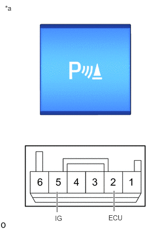
a.
1.167,4.333 1.167,3.917
true
2.333,4.313 2.333,3.896
true
0.104,0.083 0.417,0.281
0.313,0.198
10
false
*a
1.125,4.375 1.365,4.573
0.24,0.198
10
false
IG
2.219,4.365 2.625,4.583
0.406,0.219
10
false
ECU
| *a | Component without harness connected
(Back Sonar Or Clearance Sonar Switch Assembly) |
Measure the resistance according to the value(s) in the table below.
- Standard Resistance:
Tester Connection Switch Condition Specified Condition If the result is not as specified, replace the back sonar or clearance sonar switch assembly.
5 (IG) - 2 (EUC) Back Sonar Or Clearance Sonar Switch Assembly on (not protruding) Below 1 Ω Back Sonar Or Clearance Sonar Switch Assembly off (protruding) 10 kΩ or higher
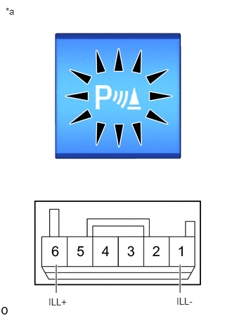
b.
0.833,4.333 0.833,3.917
true
2.667,4.333 2.667,3.917
true
0.083,0.083 0.396,0.281
0.313,0.198
10
false
*a
0.719,4.385 1.333,4.583
0.615,0.198
10
false
ILL+
2.615,4.375 3.229,4.573
0.615,0.198
10
false
ILL-
| *a | Component without harness connected
(Back Sonar Or Clearance Sonar Switch Assembly) |
Check that the switch illuminates.
i.
Apply battery voltage to the clearance sonar switch and check that the switch illuminates.
- OK:
Battery Connection Specified Condition If the result is not as specified, replace the back sonar or clearance sonar switch assembly.
Battery positive (+) → Terminal 6 (ILL+)
Battery negative (-) → Terminal 1 (ILL-)Illuminates