RM35X0E
_58
Vehicle Interior
_078336
DOOR LOCK
_0387723
DOOR CONTROL SWITCH
G
DOOR LOCK DOOR CONTROL SWITCH INSPECTION
CAUTION / NOTICE / HINT
- HINT:
- ·
Use the same procedure for RHD and LHD vehicles.
·The procedure listed below is for LHD vehicles.
PROCEDURE

 84040
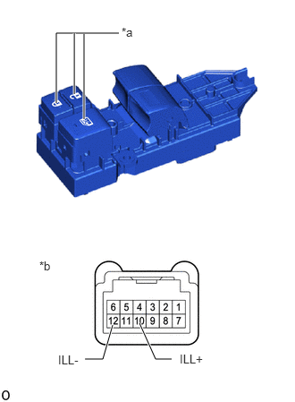
1.INSPECT MULTIPLEX NETWORK MASTER SWITCH ASSEMBLY (for LHD)
84040
1.INSPECT MULTIPLEX NETWORK MASTER SWITCH ASSEMBLY (for LHD)
a.
0.99,4.177 1.198,4.177
1.198,4.177 1.313,3.781
true
2,4.177 1.813,4.177
1.813,4.177 1.625,3.76
true
0.656,1.198 0.656,0.385
0.656,0.385 1.385,0.385
true
0.865,1.094 0.865,0.385
true
0.979,1.385 0.979,0.396
true
1.417,0.292 1.729,0.542
0.313,0.25
10
false
*a
0.458,3.01 0.771,3.167
0.313,0.156
10
false
*b
2.094,4.094 2.708,4.292
0.615,0.198
10
false
ILL+
0.677,4.104 1.292,4.302
0.615,0.198
10
false
ILL-
| *a | LED Illumination |
| *b | Component without harness connected
(Multiplex Network Master Switch Assembly) |
Check that the LED illuminates.
i.
Apply battery voltage to the multiplex network master switch assembly connector, and check that the LED illuminates.
- OK:
Battery Connection Specified Condition Battery positive (+) → Terminal 10 (ILL+)
Battery negative (-) → Terminal 12 (ILL-)LED illuminates
If the result is not as specified, replace the multiplex network master switch assembly.
84040
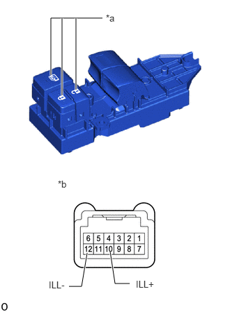
2.INSPECT MULTIPLEX NETWORK MASTER SWITCH ASSEMBLY (for RHD)
a.
1.031,4.292 1.219,4.292
1.219,4.292 1.302,3.792
true
1.938,4.25 1.719,4.25
1.719,4.25 1.646,3.771
true
0.76,1.125 0.76,0.271
0.76,0.271 1.531,0.271
true
0.927,1.427 0.927,0.271
true
1.135,1.344 1.135,0.271
true
2.031,4.177 2.573,4.375
0.542,0.198
10
false
ILL+
0.729,4.188 1.281,4.458
0.552,0.271
10
false
ILL-
0.865,2.677 1.531,3.115
0.667,0.438
10
false
*b
1.583,0.188 1.969,0.521
0.385,0.333
10
false
*a
| *a | LED Illumination |
| *b | Component without harness connected
(Multiplex Network Master Switch Assembly) |
Check that the LED illuminates.
i.
Apply battery voltage to the multiplex network master switch assembly connector, and check that the LED illuminates.
- OK:
Battery Connection Specified Condition Battery positive (+) → Terminal 10 (ILL+)
Battery negative (-) → Terminal 12 (ILL-)LED illuminates
If the result is not as specified, replace the multiplex network master switch assembly.