DOOR / HATCH POWER SLIDE DOOR CONTROL SWITCH INSPECTION
PROCEDURE

 84963
1.INSPECT NO. 1 POWER SLIDE DOOR CONTROL SWITCH
84963
1.INSPECT NO. 1 POWER SLIDE DOOR CONTROL SWITCH
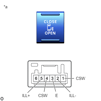
| *a | Component without harness connected
(No. 1 Power Slide Door Control Switch) |
Check the operation of the No. 1 power slide door control switch.
Measure the resistance according to the value(s) in the table below.
- Standard Resistance:
Tester Connection Switch Condition Specified Condition 1 (CSW) - 3 (E) "CLOSE" Switch (ON) Below 1 Ω "CLOSE" Switch (OFF) 10 kΩ or higher 4 (CSW) - 3 (E) "OPEN" Switch (ON) Below 1 Ω "OPEN" Switch (OFF) 10 kΩ or higher
If the result is not as specified, replace the power slide door control switch.
Check the illumination of the No. 1 power slide door control switch.
Apply battery voltage to the switch connector and check that the power slide door control switch illuminates.
- OK:
Battery Connection Specified Condition Battery positive (+) → Terminal 5 (ILL+)
Battery negative (-) → Terminal 2 (ILL-)Illumination illuminates
If the result is not as specified, replace the No. 1 power slide door control switch.
84963A
2.INSPECT NO. 2 POWER SLIDE DOOR CONTROL SWITCH

| *a | Component without harness connected
(No. 2 Power Slide Door Control Switch) |
Check the operation of the No. 2 power slide door control switch.
Measure the resistance according to the value(s) in the table below.
- Standard Resistance:
Tester Connection Switch Condition Specified Condition 1 (CSW) - 3 (E) "CLOSE" Switch (ON) Below 1 Ω "CLOSE" Switch (OFF) 10 kΩ or higher 4 (CSW) - 3 (E) "OPEN" Switch (ON) Below 1 Ω "OPEN" Switch (OFF) 10 kΩ or higher
If the result is not as specified, replace the power slide door control switch.
Check the illumination of the No. 2 power slide door control switch.
Apply battery voltage to the switch connector and check that the power slide door control switch illuminates.
- OK:
Battery Connection Specified Condition Battery positive (+) → Terminal 5 (ILL+)
Battery negative (-) → Terminal 2 (ILL-)Illumination illuminates
If the result is not as specified, replace the No. 2 power slide door control switch.