7GR-FKS COOLING THERMOSTAT INSTALLATION
PROCEDURE

 16031
1.INSTALL WATER INLET SUB-ASSEMBLY WITH THERMOSTAT
16031
1.INSTALL WATER INLET SUB-ASSEMBLY WITH THERMOSTAT
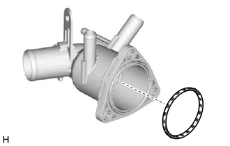
Install a new gasket to the water inlet sub-assembly with thermostat.
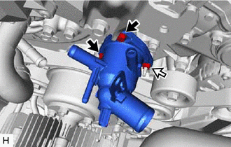

|
Bolt |

|
Nut |
Install the water inlet sub-assembly with thermostat to the engine water pump assembly with the 2 bolts and nut.
- Torque:
- 10 N*m (102 kgf*cm, 7 ft.*lbf)
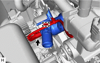
Connect the connector and attach the clamp.
16281
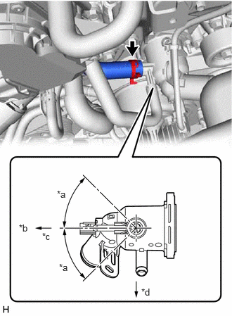
2.CONNECT NO. 4 WATER BY-PASS HOSE
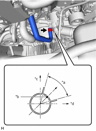
| *a | 60° |
| *b | Paint Mark |
| *c | Upper Side |
| *d | LH Side |
Connect the No. 4 water by-pass hose to the water inlet sub-assembly with thermostat, and slide the clip to secure the hose.
- NOTICE:
- ·
Make sure the No. 4 water by-pass hose is securely inserted to the stopper.
·Position the clip so that it is 1 to 5 mm (0.0394 to 0.197 in.) away from the end of the water hose.
·The clip and paint mark face the same direction.
16267
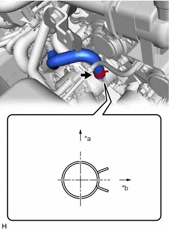
3.CONNECT NO. 3 WATER BY-PASS HOSE
| *a | 45° |
| *b | Direction of Tab of Clip |
| *c | Front Side |
| *d | LH Side |
Connect the No. 3 water by-pass hose to the water inlet sub-assembly with thermostat, and slide the clip to secure the hose.
- NOTICE:
- ·
Make sure the No. 3 water by-pass hose is securely inserted to the stopper.
·Position the clip so that it is 1 to 5 mm (0.0394 to 0.197 in.) away from the end of the water hose.
16295
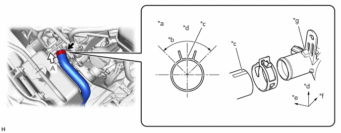
4.CONNECT NO. 7 WATER BY-PASS HOSE
| *a | Rear Side |
| *b | LH Side |
Connect the No. 7 water by-pass hose to the water inlet sub-assembly with thermostat, and slide the clip to secure the hose.
- NOTICE:
- ·
Make sure the No. 7 water by-pass hose is securely inserted to the stopper.
·Position the clip so that it is 1 to 5 mm (0.0394 to 0.197 in.) away from the end of the water hose.
·The clip and paint mark face the same direction.
16572D
5.CONNECT NO. 2 RADIATOR HOSE
Connect the No. 2 radiator hose to the water inlet sub-assembly with thermostat, and slide the clip to secure the hose.
- NOTICE:
- ·
Make sure the No. 2 radiator hose is securely inserted to the stopper.
·Position the clip so that it is 2 to 5 mm (0.0787 to 0.197 in.) away from the end of the water hose.
·Install so that the No. 2 radiator hose paint mark is aligned with the protrusion of the water inlet sub-assembly with thermostat.
| *a | View A | *b | 90° |
| *c | Paint Mark | *d | Upper Side |
| *e | Front Side | *f | RH Side |
| *g | Protrusion of the Water Inlet Sub-assembly with Thermostat | - | - |
6.ADD ENGINE COOLANT
7.INSPECT FOR COOLANT LEAK
51405A
8.INSTALL NO. 1 ENGINE UNDER COVER SUB-ASSEMBLY
52618
9.INSTALL LOWER FRONT BUMPER ABSORBER
51406A
10.INSTALL NO. 2 ENGINE UNDER COVER SUB-ASSEMBLY (w/ No. 2 Engine Under Cover Sub-assembly)