7GR-FKS BATTERY / CHARGING GENERATOR REASSEMBLY
PROCEDURE

 27310
1.INSTALL GENERATOR DRIVE END FRAME BEARING
27310
1.INSTALL GENERATOR DRIVE END FRAME BEARING
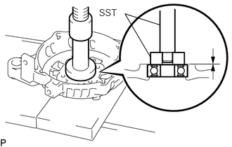
Using SST and a press, press in a new generator drive end frame bearing.
- SST
- 09950-60011 (09951-00470)
09950-70010 (09951-07100)
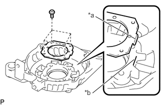
| *a | Tab |
| *b | Cutout |
Fit the tabs on the retainer plate into the cutouts on the drive end frame to install the retainer plate.
Install the 4 screws.
- Torque:
- 2.3 N*m (23 kgf*cm, 20 in.*lbf)
27330
2.INSTALL GENERATOR ROTOR ASSEMBLY
Place the generator drive end frame on the generator pulley.
Install the generator rotor assembly to the generator drive end frame.
27444
3.INSTALL GENERATOR BEARING COVER PACKING
- NOTICE:
-
A new generator coil assembly comes with a generator bearing cover packing. Therefore, it is not necessary to install a new generator bearing cover packing when installing a new generator coil assembly.
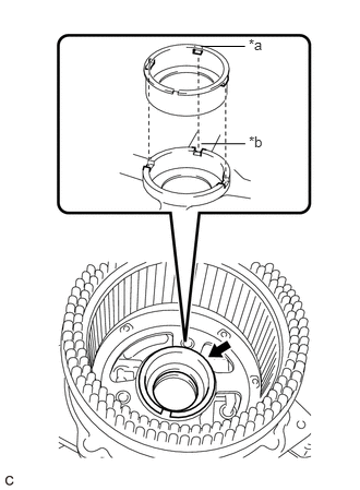
| *a | Protrusion |
| *b | Groove |
Install a new generator bearing cover packing to the generator coil assembly.
- NOTICE:
-
Align the protrusion of the generator bearing cover packing with the groove of the generator coil assembly when installing.
27360
4.INSTALL GENERATOR COIL ASSEMBLY
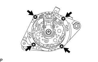
Temporarily install the generator coil assembly to the generator drive end frame with the 4 through bolts.
- NOTICE:
-
Because the generator coil assembly must be installed with a press after the through bolts have first been temporarily tightened, do not attempt to install the generator coil assembly by tightening the through bolts only.
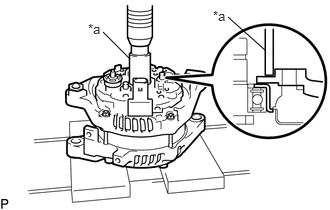
| *a | 21 mm Deep Socket Wrench |
Using a 21 mm deep socket wrench and press, slowly press in the generator coil assembly.
Tighten the 4 through bolts.
- Torque:
- 5.6 N*m (57 kgf*cm, 50 in.*lbf)
27370
5.INSTALL GENERATOR BRUSH HOLDER ASSEMBLY
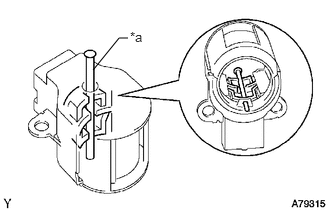
| *a | Pin |
While pushing the 2 brushes into the generator brush holder assembly, insert a pin with a diameter of 1.0 mm (0.0394 in.) into the brush holder hole.
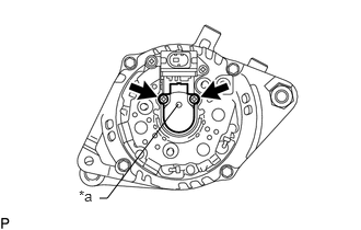
| *a | Pin |
Install the generator brush holder assembly to the generator coil assembly with the 2 screws.
- Torque:
- 1.8 N*m (18 kgf*cm, 16 in.*lbf)
Pull out the pin from the generator brush holder assembly.
27039
6.INSTALL GENERATOR REAR END COVER
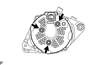
Install the generator rear end cover to the generator coil assembly with the 3 bolts.
- Torque:
- 4.6 N*m (47 kgf*cm, 41 in.*lbf)
27387
7.INSTALL TERMINAL INSULATOR
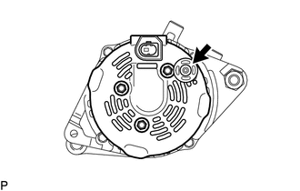
Install the terminal insulator to the generator coil assembly.
- NOTICE:
-
Make sure the terminal insulator is installed facing the proper direction.
27411
8.INSTALL GENERATOR PULLEY
Temporarily install the generator pulley by hand.
Mount the generator assembly in the vise between aluminum plates.
- NOTICE:
-
Do not overtighten the vise.
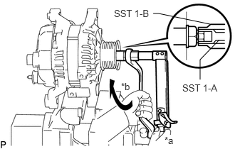
| *a | Hold |
| *b | Turn |
Install SST 1-A and B to the generator pulley shaft.
- SST
- 09820-63011 (09820-06010, 09820-06021)
- Torque:
- 39 N*m (398 kgf*cm, 29 ft.*lbf)
Install SST 1-B to SST 1-A.
- SST
- 09820-63011 (09820-06010, 09820-06021)
Hold SST 1-A with a torque wrench and turn SST 1-B clockwise with the specified torque.
- Torque:
- 39 N*m (398 kgf*cm, 29 ft.*lbf)
- NOTICE:
-
Make sure that SST is secured to the generator rotor shaft.
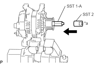
| *a | Insert |
Insert SST 2 and attach it to the generator pulley nut.
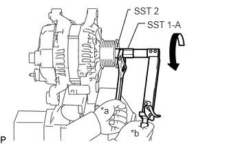
| *a | Hold |
| *b | Turn |
Tighten the generator pulley nut by turning SST 1-A as shown in the illustration.
- Torque:
- 132.5 N*m (1351 kgf*cm, 98 ft.*lbf)
Remove SST 2 from the generator pulley shaft.
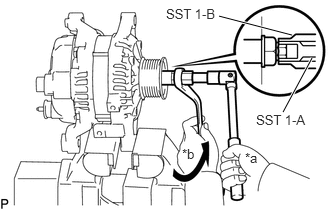
| *a | Hold |
| *b | Turn |
Turn SST 1-B as shown in the illustration and remove SST 1-A and B.
Turn the generator pulley and check that the generator pulley moves smoothly.
Remove the generator assembly from the vise.