7GR-FKS BATTERY / CHARGING GENERATOR DISASSEMBLY
PROCEDURE

 27411
1.REMOVE GENERATOR PULLEY
27411
1.REMOVE GENERATOR PULLEY
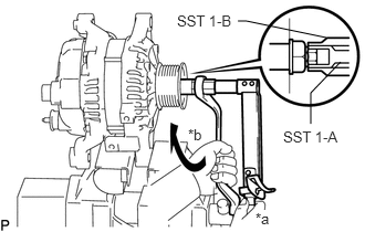
| *a | Hold |
| *b | Turn |
Mount the generator assembly in the vise between aluminum plates.
- NOTICE:
-
Do not overtighten the vise.
Install SST 1-A to the generator pulley shaft.
- SST
- 09820-63011 (09820-06010, 09820-06021)
Install SST 1-B to SST 1-A.
Hold SST 1-A with a torque wrench and turn SST 1-B clockwise with the specified torque.
- Torque:
- 39 N*m (398 kgf*cm, 29 ft.*lbf)
- NOTICE:
-
Make sure that SST is secured to the generator rotor shaft.
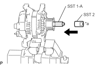
| *a | Insert |
Insert SST 2 and attach it to the generator pulley nut.
- SST
- 09820-63011 (09820-06010, 09820-06021)
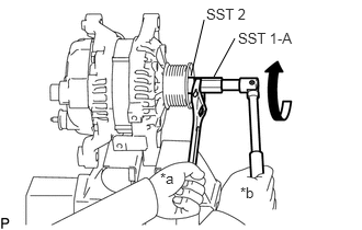
| *a | Hold |
| *b | Turn |
To loosen the generator pulley nut, turn SST 1-A as shown in the illustration.
- NOTICE:
-
To prevent damage to the generator rotor shaft, do not loosen the generator pulley nut more than one-self of a turn.
Remove SST 2 from the generator pulley shaft.
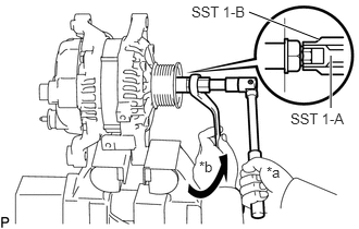
| *a | Hold |
| *b | Turn |
Turn SST 1-B as shown in the illustration and remove SST 1-A and B.
Remove the pulley nut and generator pulley.
Remove the generator assembly from the vise.
27387
2.REMOVE TERMINAL INSULATOR
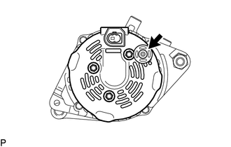
Remove the terminal insulator from the generator coil assembly.
27039
3.REMOVE GENERATOR REAR END COVER
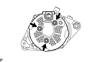
Place the generator assembly on the generator pulley.
Remove the 3 bolts and generator rear end cover from the generator coil assembly.
27370
4.REMOVE GENERATOR BRUSH HOLDER ASSEMBLY
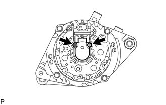
Remove the 2 screws and generator brush holder assembly from the generator coil assembly.
27360
5.REMOVE GENERATOR COIL ASSEMBLY
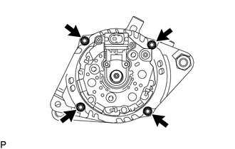
Remove the 4 through bolts.
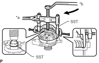
| *a | Hold |
| *b | Turn |
Using SST, remove the generator coil assembly.
- SST
- 09950-40011 (09951-04020, 09952-04010, 09953-04020, 09954-04010, 09955-04071, 09957-04010, 09958-04010)
27444
6.REMOVE GENERATOR BEARING COVER PACKING
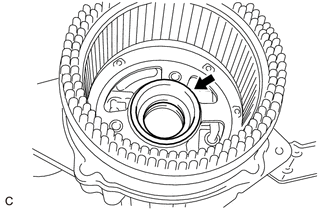
Remove the generator bearing cover packing.
- NOTICE:
-
If the generator bearing cover packing breaks, remove all broken pieces.
- HINT:
-
The generator bearing cover packing may be installed on the generator rotor assembly.
27330
7.REMOVE GENERATOR ROTOR ASSEMBLY
Remove the generator rotor assembly from the generator drive end frame.
27310
8.INSPECT GENERATOR DRIVE END FRAME BEARING
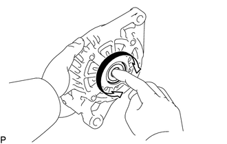
Check that the generator drive end frame bearing is not rough or worn and that it rotates smoothly.
If necessary, replace the generator drive end frame bearing.
27310
9.REMOVE GENERATOR DRIVE END FRAME BEARING
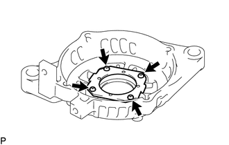
Remove the 4 screws and retainer plate from the generator drive end frame.
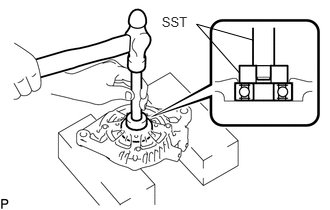
Using SST and a hammer, tap out the generator drive end frame bearing from the generator drive end frame.
- SST
- 09950-60011 (09951-00250)
09950-70010 (09951-07100)