☰ Toyota HiAce☰ فهرستAudio / Visual / Telematics › PARK ASSIST / MONITORING › REAR VIEW MONITOR SYSTEM(for Inner Rear View Mirror Type)
RM35X0E
_56
Audio / Visual / Telematics
_079315
PARK ASSIST / MONITORING
_0385737
REAR VIEW MONITOR SYSTEM(for Inner Rear View Mirror Type)
U
PARK ASSIST / MONITORING REAR VIEW MONITOR SYSTEM(for Inner Rear View Mirror Type) TERMINALS OF ECU
CHECK INNER REAR VIEW MIRROR ASSEMBLY

3.385,0.208 3.76,0.438
0.375,0.229
3.458,0.24 3.823,0.438
0.365,0.198
10
false
a7
a.
Disconnect the a7 inner rear view mirror assembly connector.
b.
Measure the voltage and resistance according to the value(s) in the table below.
| Terminal No. (Symbol) | Wiring Color | Terminal Description | Condition | Specified Condition |
|---|---|---|---|---|
| a7-6 (IG) - a7-3 (E) | P - W-B | Ignition switch signal | Ignition switch off | Below 1 V |
| Ignition switch ON | 11 to 14 V | |||
| a7-3 (E) - Body ground | W-B - Body ground | Ground | Always | Below 1 Ω |
c.
Reconnect the a7 inner rear view mirror assembly connector.
d.
Measure the voltage, resistance and waveform according to the value(s) in the table below.
| Terminal No. (Symbol) | Wiring Color | Terminal Description | Condition | Specified Condition |
|---|---|---|---|---|
| a7-5 (REV) - a7-3 (E) | L - W-B | Reverse signal | Ignition switch ON, shift lever in R | 11 to 14 V |
| Ignition switch ON, shift lever not in R | Below 1 V | |||
| a7-1 (CV-) - Body ground | B - Body ground | Shielded | Always | Below 1 V |
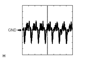
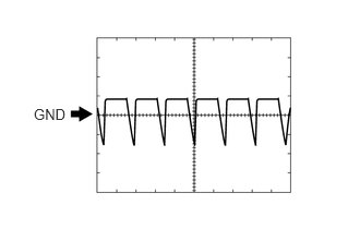
| a7-2 (CV+) - a7-1 (CV-) | R - B | Display signal | Ignition switch ON, shift lever in R | Pulse generation
(See waveform 1) |
| Ignition switch ON, shift lever in R, screen blacked out by covering camera lens | Pulse generation
(See waveform 2) |
|||
| a7-8 (CGND) - a7-3 (E) | Shielded - W-B | Rear television camera ground (shield) | Always | Below 1 Ω |
| a7-7 (CB+) - a7-8 (CGND) | W - Shielded | Power source | Ignition switch ON, shift lever in R | 5.5 to 7.05 V |
e.
0.292,1.01 0.625,1.156
0.333,0.146
10
false
GND
Using an oscilloscope, check waveform 1.
| Item | Content |
|---|---|
| Terminal No. (Symbol) | a7-2 (CV+) - a7-1 (CV-) |
| Tool Setting | 200 mV/DIV., 50 μsec./DIV. |
| Condition | Ignition switch ON, shift lever in R |
f.
0.323,1.01 0.656,1.156
0.333,0.146
10
false
GND
Using an oscilloscope, check waveform 2.
| Item | Content |
|---|---|
| Terminal No. (Symbol) | a7-2 (CV+) - a7-1 (CV-) |
| Tool Setting | 200 mV/DIV., 50 μsec./DIV. |
| Condition | Ignition switch ON, shift lever in R, screen blacked out by covering camera lens |