RM35X0E _56 Audio / Visual / Telematics _079315 PARK ASSIST / MONITORING _0385738 BLIND SPOT MONITOR SYSTEM J

PARK ASSIST / MONITORING  BLIND SPOT MONITOR SYSTEM  Power Source Circuit  


DESCRIPTION

This circuit provides power to operate the blind spot monitor sensor.

WIRING DIAGRAM
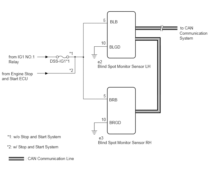
E311018E04
0.292,1.844 1.198,2.24 0.906,0.396 10 false from IG1 NO.1 Relay 3.313,4.75 5.552,5.208 2.24,0.458 10 false Blind Spot Monitor Sensor RH 3.302,2.167 5.458,2.604 2.156,0.438 10 false Blind Spot Monitor Sensor LH 3.302,2.01 3.781,2.281 0.479,0.271 10 false e2 3.344,4.594 3.802,5.198 0.458,0.604 10 false e3 6.094,0.865 6.625,1.073 0.531,0.208 10 false to CAN 3.688,3.302 4.323,3.646 0.635,0.344 10 false BRB 3.698,4.073 4.333,4.417 0.635,0.344 10 false BRGD 3.417,1.375 4.052,1.719 0.635,0.344 10 false 10 3.49,0.604 4.125,0.948 0.635,0.344 10 false 5 1.688,1.99 2.469,2.198 0.781,0.208 10 false DSS-IG1*1 3.719,0.656 4.354,1 0.635,0.344 10 false BLB 3.698,1.51 4.333,1.854 0.635,0.344 10 false BLGD 3.5,3.167 4.135,3.51 0.635,0.344 10 false 5 3.427,3.969 4.063,4.313 0.635,0.344 10 false 10 0.865,5.292 4.531,5.49 3.667,0.198 10 false : CAN Communication Line 2.344,1.729 2.979,2.073 0.635,0.344 10 false *1 2.344,2.302 2.979,2.646 0.635,0.344 10 false *2 0.25,4.552 3.917,4.75 3.667,0.198 10 false *1: w/o Stop and Start System 0.24,4.896 3.906,5.094 3.667,0.198 10 false *2: w/ Stop and Start System 0.063,2.417 1.177,3.104 1.115,0.688 10 false from Engine Stop and Start ECU 6.073,1.042 7.052,1.604 0.979,0.563 10 false Communication System

CAUTION / NOTICE / HINT

HINT:
·

w/o Stop and Start system:

Inspect the fuses for circuits related to this system before performing the following procedure.

·

w/ Stop and Start system:

The blind spot monitor system troubleshooting procedure is based on the premise that the stop and start system is operating normally. Check the stop and start system first before troubleshooting the blind spot monitor system.

Click hereEngine / Hybrid System>STOP AND START>STOP AND START SYSTEM>HOW TO PROCEED WITH TROUBLESHOOTING


PROCEDURE

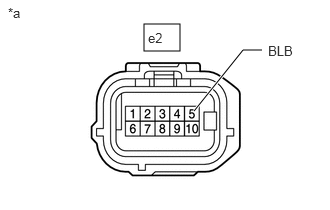
1.CHECK HARNESS AND CONNECTOR (BLIND SPOT MONITOR SENSOR LH POWER SOURCE)
a.
E406932C18
1.5,0.25 1.875,0.531 0.375,0.281 2.021,1.156 2.531,0.521 2.531,0.521 2.729,0.521 true 0.083,0.052 0.396,0.25 0.313,0.198 10 false *a 1.542,0.313 1.948,0.51 0.406,0.198 10 false e2 2.792,0.448 3.156,0.656 0.365,0.208 10 false BLB
*a Front view of wire harness connector
(to Blind Spot Monitor Sensor LH)


Disconnect the blind spot monitor sensor LH connector.


b.

Measure the voltage according to the value(s) in the table below.

Standard Voltage:
Tester Connection Switch Condition Specified Condition
e2-5 (BLB) - Body ground Ignition switch ON 10.5 to 16 V*1
11 to 14 V*2
e2-5 (BLB) - Body ground Ignition switch off Below 1 V


*1: w/ Stop and Start System

*2: w/o Stop and Start System


Result:
Result Proceed to
OK A
NG (w/o Stop and Start System) B
NG (w/ Stop and Start System) C


A

2.CHECK HARNESS AND CONNECTOR (BLIND SPOT MONITOR SENSOR LH - BODY GROUND)

B

REPAIR OR REPLACE HARNESS OR CONNECTOR

C

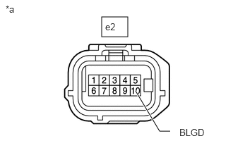
2.CHECK HARNESS AND CONNECTOR (BLIND SPOT MONITOR SENSOR LH - BODY GROUND)
a.
E406932C19
1.5,0.25 1.885,0.542 0.385,0.292 2,1.344 2.354,1.938 2.354,1.938 2.51,1.938 true 0.083,0.052 0.396,0.25 0.313,0.198 10 false *a 1.552,0.313 1.969,0.51 0.417,0.198 10 false e2 2.646,1.875 3.083,2.063 0.438,0.188 10 false BLGD
*a Front view of wire harness connector
(to Blind Spot Monitor Sensor LH)


Disconnect the blind spot monitor sensor LH connector.


b.

Measure the resistance according to the value(s) in the table below.

Standard Resistance:
Tester Connection Condition Specified Condition
e2-10 (BLGD) - Body ground Always Below 1 Ω


Result:
Proceed to
OK
NG


OK

3.CHECK HARNESS AND CONNECTOR (BLIND SPOT MONITOR SENSOR RH POWER SOURCE)

NG

REPAIR OR REPLACE HARNESS OR CONNECTOR

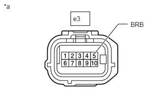
3.CHECK HARNESS AND CONNECTOR (BLIND SPOT MONITOR SENSOR RH POWER SOURCE)
a.
E406932C20
1.5,0.25 1.906,0.542 0.406,0.292 2,1.146 2.51,0.51 2.51,0.51 2.708,0.51 true 0.083,0.052 0.396,0.25 0.313,0.198 10 false *a 1.552,0.313 1.917,0.531 0.365,0.219 10 false e3 2.771,0.438 3.177,0.625 0.406,0.188 10 false BRB
*a Front view of wire harness connector
(to Blind Spot Monitor Sensor RH)


Disconnect the blind spot monitor sensor RH connector.


b.

Measure the voltage according to the value(s) in the table below.

Standard Voltage:
Tester Connection Switch Condition Specified Condition
e3-5 (BRB) - Body ground Ignition switch ON 10.5 to 16 V*1
11 to 14 V*2
e3-5 (BRB) - Body ground Ignition switch off Below 1 V


*1: w/ Stop and Start System

*2: w/o Stop and Start System


Result:
Result Proceed to
OK A
NG (w/o Stop and Start System) B
NG (w/ Stop and Start System) C


A

4.CHECK HARNESS AND CONNECTOR (BLIND SPOT MONITOR SENSOR RH - BODY GROUND)

B

REPAIR OR REPLACE HARNESS OR CONNECTOR

C

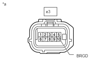
4.CHECK HARNESS AND CONNECTOR (BLIND SPOT MONITOR SENSOR RH - BODY GROUND)
a.
E406932C21
1.5,0.25 1.938,0.542 0.438,0.292 2.042,1.354 2.365,1.865 2.365,1.865 2.51,1.865 true 0.083,0.052 0.396,0.25 0.313,0.198 10 false *a 1.563,0.313 1.927,0.521 0.365,0.208 10 false e3 2.604,1.823 3.063,2.01 0.458,0.188 10 false BRGD
*a Front view of wire harness connector
(to Blind Spot Monitor Sensor RH)


Disconnect the blind spot monitor sensor RH connector.


b.

Measure the resistance according to the value(s) in the table below.

Standard Resistance:
Tester Connection Condition Specified Condition
e3-10 (BRGD) - Body ground Always Below 1 Ω


Result:
Proceed to
OK
NG


OK

NG

REPAIR OR REPLACE HARNESS OR CONNECTOR