AC60E AUTOMATIC TRANSMISSION / TRANSAXLE AUTOMATIC TRANSMISSION UNIT(for 7GR-FKS) INSPECTION
PROCEDURE

 35605A
1.INSPECT DIRECT CLUTCH DRUM SUB-ASSEMBLY
35605A
1.INSPECT DIRECT CLUTCH DRUM SUB-ASSEMBLY
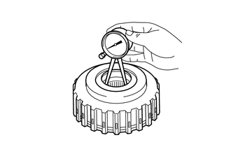
Using a caliper gauge, measure the inside diameter of the direct clutch drum sub-assembly bushing.
- Standard Inside Diameter:
59.515 to 59.540 mm (2.3432 to 2.3440 in.)
If the inside diameter is not as specified, replace the direct clutch drum sub-assembly.
2.INSPECT INPUT SHAFT SUB-ASSEMBLY
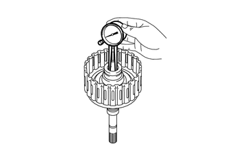
Using a caliper gauge, measure the inside diameter of the input shaft sub-assembly bushing.
- Standard Inside Diameter:
20.000 to 20.025 mm (0.7874 to 0.7883 in.)
If the inside diameter is not as specified, replace the input shaft sub-assembly.
35061
3.INSPECT FORWARD CLUTCH HUB SUB-ASSEMBLY
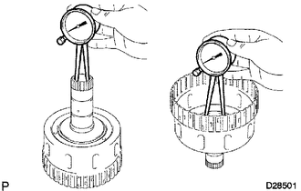
Using a caliper gauge, measure the inside diameter of the forward clutch hub sub-assembly bushing.
- Standard Inside Diameter:
26.037 to 26.062 mm (1.0251 to 1.0260 in.)
If the inside diameter is not as specified, replace the forward clutch hub sub-assembly.
35709J
4.INSPECT SUN GEAR INPUT DRUM SUB-ASSEMBLY
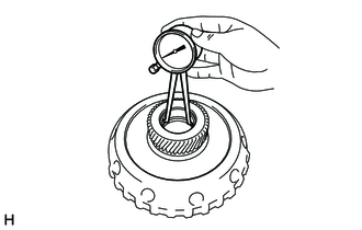
Using a caliper gauge, measure the inside diameter of the sun gear input drum sub-assembly bushing.
- Standard Inside Diameter:
35.811 to 35.835 mm (1.4099 to 1.4108 in.)
If the inside diameter is not as specified, replace the sun gear input drum sub-assembly.
35720
5.INSPECT FRONT PLANETARY GEAR ASSEMBLY

Using a caliper gauge, measure the inside diameter of the front planetary gear assembly bushing.
- Standard Inside Diameter:
35.811 to 35.835 mm (1.4099 to 1.4108 in.)
If the inside diameter is not as specified, replace the front planetary gear assembly.
35076C
6.INSPECT FRONT PLANETARY RING GEAR FLANGE SUB-ASSEMBLY
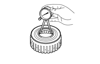
Using a caliper gauge, measure the inside diameter of the front planetary ring gear flange sub-assembly bushing.
- Standard Inside Diameter:
54.038 to 54.063 mm (2.1275 to 2.1284 in.)
If the inside diameter is not as specified, replace the front planetary ring gear flange sub-assembly.
35077D
7.INSPECT REAR PLANETARY RING GEAR FLANGE SUB-ASSEMBLY
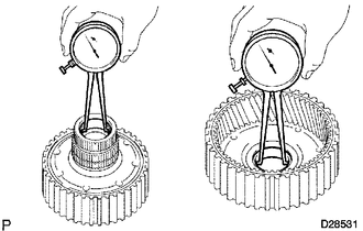
Using a caliper gauge, measure the inside diameter of the rear planetary ring gear flange sub-assembly bushing.
- Standard Inside Diameter:
32.176 to 32.201 mm (1.2668 to 1.2677 in.)
If the inside diameter is not as specified, replace the rear planetary ring gear flange sub-assembly.
35750
8.INSPECT CENTER PLANETARY GEAR ASSEMBLY
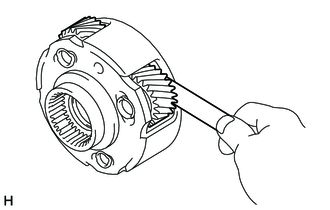
Using a feeler gauge, measure the center planetary gear pinion thrust clearance.
- Standard Clearance:
0.12 to 0.68 mm (0.00473 to 0.0267 in.)
If the clearance is not as specified, replace the center planetary gear assembly.
35760
9.INSPECT REAR PLANETARY GEAR ASSEMBLY
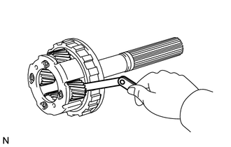
Using a feeler gauge, measure the rear planetary gear pinion thrust clearance.
- Standard Clearance:
0.2 to 0.6 mm (0.00788 to 0.0236 in.)
If the clearance is not as specified, replace the rear planetary gear assembly.
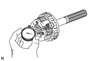
Using a caliper gauge, measure the inside diameter of the rear planetary gear bushing.
- Standard Inside Diameter:
20.000 to 20.025 mm (0.7874 to 0.7883 in.)
If the inside diameter is not as specified, replace the rear planetary gear assembly.
35770C
10.INSPECT NO. 3 ONE-WAY CLUTCH ASSEMBLY
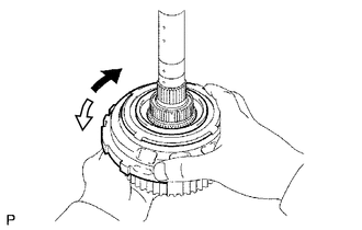

|
Lock |

|
Free |
Hold the rear planetary ring gear and turn the No. 3 one-way clutch assembly.
Check that the No. 3 one-way clutch assembly turns freely when turned counterclockwise and locks when turned clockwise.
If there is a problem with the No. 3 one-way clutch assembly, replace it.
35713
11.INSPECT INTERMEDIATE SHAFT
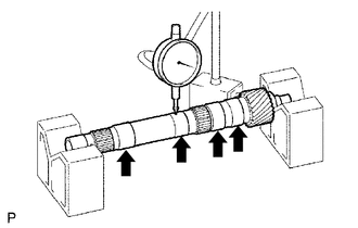
Using a dial indicator, check the intermediate shaft runout.
- Standard Runout:
0.03 mm (0.00118 in.)
If the runout is more than the standard, replace the intermediate shaft with a new one.
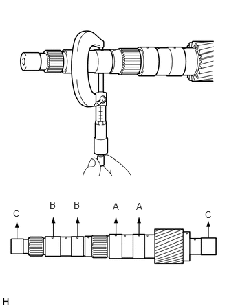
Using a micrometer, check the outer diameter of the intermediate shaft at each point shown in the illustration.
- Standard Diameter:
- A:
32.062 to 32.075 mm (1.2623 to 1.2627 in.)
- B:
25.962 to 25.975 mm (1.0222 to 1.0226 in.)
- C:
19.963 to 19.976 mm (0.7860 to 0.7864 in.)
If the outer diameter is more than the standard, replace the intermediate shaft with a new one.
35603A
12.INSPECT FORWARD CLUTCH RETURN SPRING SUB-ASSEMBLY

Using a vernier caliper, measure the free length of the forward clutch return spring sub-assembly including the spring seat.
- Standard Free Length:
26.74 mm (1.053 in.)
If the free length is more than the standard free length, replace the forward clutch return spring sub-assembly.
35604
13.INSPECT DIRECT CLUTCH RETURN SPRING SUB-ASSEMBLY
Using a vernier caliper, measure the free length of the direct clutch return spring sub-assembly including the spring seat.
- Standard Free Length:
22.14 mm (0.872 in.)
If the free length is more than the standard free length, replace the direct clutch return spring sub-assembly.
35608J
14.INSPECT NO. 1 BRAKE PISTON RETURN SPRING SUB-ASSEMBLY
Using a vernier caliper, measure the free length of the No. 1 brake piston return spring sub-assembly including the spring seat.
- Standard Free Length:
16.72 mm (0.658 in.)
If the free length is more than the standard free length, replace the No. 1 brake piston return spring sub-assembly.
35045
15.INSPECT NO. 2 BRAKE PISTON RETURN SPRING SUB-ASSEMBLY
Using a vernier caliper, measure the free length of the No. 2 brake piston return spring sub-assembly including the spring seat.
- Standard Free Length:
16.68 mm (0.657 in.)
If the free length is more than the standard free length, replace the No. 2 brake piston return spring sub-assembly.
35068
16.INSPECT 1ST AND REVERSE BRAKE RETURN SPRING SUB-ASSEMBLY
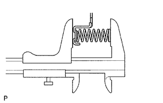
Using a vernier caliper, measure the free length of the 1st and reverse brake return spring sub-assembly including the spring seat.
- Standard Free Length:
23.74 mm (0.935 in.)
If the free length is more than the standard free length, replace the 1st and reverse return spring sub-assembly.
35633B
17.INSPECT NO. 1 CLUTCH DISC (FORWARD CLUTCH DISC)
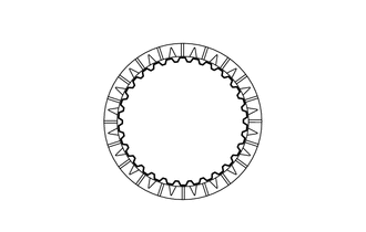
Check if the contact surfaces of the No. 1 clutch discs, No. 1 clutch plates and No. 1 clutch flange are worn or burnt.
If necessary, replace them.
- NOTICE:
- ·
If the lining of any No. 1 clutch disc is peeled or discolored, or even if part of a groove is damaged, replace all the No. 1 clutch discs.
·Before installing new No. 1 clutch discs, soak them in ATF for at least 15 minutes.
35667A
18.INSPECT NO. 2 CLUTCH DISC (DIRECT CLUTCH DISC)
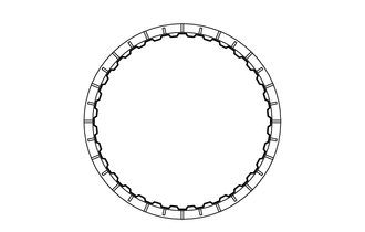
Check if the contact surfaces of the No. 2 clutch discs, No. 2 clutch plates and No. 2 clutch flange are worn or burnt.
If necessary, replace them.
- NOTICE:
- ·
If the lining of any No. 2 clutch disc is peeled or discolored, or even if part of a groove is damaged, replace all the No. 2 clutch discs.
·Before installing new No. 2 clutch discs, soak them in ATF for at least 15 minutes.
35681A
19.INSPECT NO. 1 BRAKE DISC
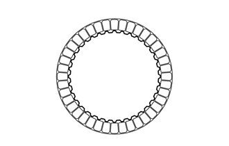
Check if the contact surfaces of the No. 1 brake discs, No. 1 brake plates and No. 1 brake flange are worn or burnt.
If necessary, replace them.
- NOTICE:
- ·
If the lining of any No. 1 brake disc is peeled or discolored, or even if part of a groove is damaged, replace all the No. 1 brake discs.
·Before installing new No. 1 brake discs, soak them in ATF for at least 15 minutes.
35682A
20.INSPECT NO. 2 BRAKE DISC
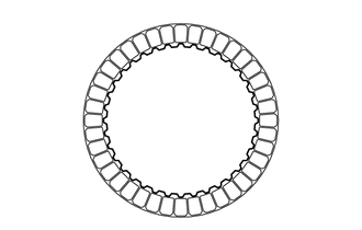
Check if the contact surfaces of the No. 2 brake discs, No. 2 brake plates and No. 2 brake flanges are worn or burnt.
If necessary, replace them.
- NOTICE:
- ·
If the lining of any No. 2 brake disc is peeled or discolored, or even if part of a groove is damaged, replace all the No. 2 brake discs.
·Before installing new No. 2 brake discs, soak them in ATF for at least 15 minutes.
35684
21.INSPECT NO. 4 BRAKE DISC
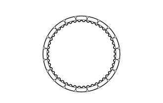
Check if the contact surfaces of the No. 4 brake discs, No. 4 brake plates and No. 4 brake flanges are worn or burnt.
If necessary, replace them.
- NOTICE:
- ·
If the lining of any No. 4 brake disc is peeled or discolored, or even if part of a groove is damaged, replace all the No. 4 brake discs.
·Before installing new No. 4 brake discs, soak them in ATF for at least 15 minutes.
35635
22.INSPECT CLEARANCE OF NO. 1 CLUTCH (FORWARD CLUTCH)
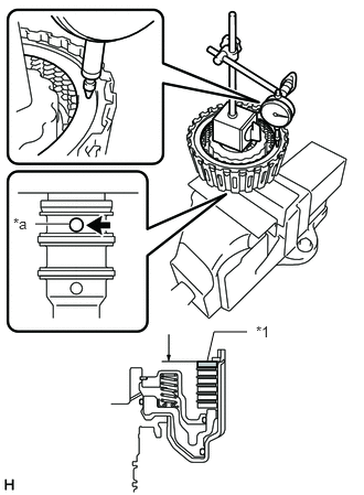
| *1 | Selected Forward Clutch Flange |
| *a | Oil Hole |
Using a dial indicator, measure the clearance of the No. 1 clutch at several points while applying compressed air (196 kPa, 2.0 kgf/cm2, 28 psi) to the oil hole as shown in the illustration, and calculate the average.
- Standard Clearance:
0.75 to 1.05 mm (0.0296 to 0.0413 in.)
If the clearance is not as specified, select and install an appropriate forward clutch flange that will bring the clearance within the specified range.
- HINT:
-
There are forward clutch flanges of different thicknesses.
- Forward Clutch Flange Thickness:
Part No. Thickness (mm (in.)) 35635-71010 3.0 (0.118) 35635-71020 3.1 (0.122) 35635-71030 3.2 (0.126) 35635-71040 3.3 (0.130) 35635-71050 3.4 (0.134) 35635-71060 3.5 (0.138) 35635-71070 3.6 (0.142) 35635-71080 3.7 (0.146) 35635-71090 3.8 (0.150) 35635-71100 3.9 (0.154) 35635-71110 4.0 (0.157) 35635-71120 4.1 (0.161) 35635-71130 4.2 (0.165)
35675C
23.INSPECT CLEARANCE OF NO. 2 CLUTCH (DIRECT CLUTCH)
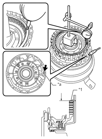
| *1 | Selected Direct Clutch Flange |
| *a | Oil Hole |
Using a dial indicator, measure the clearance of the No. 2 clutch at several points while applying compressed air (196 kPa, 2.0 kgf/cm2, 28 psi) to the oil hole as shown in the illustration, and calculate the average.
- Standard Clearance:
0.52 to 0.82 mm (0.0205 to 0.0323 in.)
If the clearance is not as specified, select and install an appropriate direct clutch flange that will bring the clearance within the specified range.
- HINT:
-
There are direct clutch flanges of different thicknesses.
- Direct Clutch Flange Thickness:
Part No. Thickness (mm (in.)) 35675-71010 3.0 (0.118) 35675-71020 3.1 (0.122) 35675-71030 3.2 (0.126) 35675-71040 3.3 (0.130) 35675-71050 3.4 (0.134) 35675-71060 3.5 (0.138) 35675-71070 3.6 (0.142) 35675-71080 3.7 (0.146) 35675-71090 3.8 (0.150)
35676B
24.INSPECT CLEARANCE OF NO. 1 BRAKE
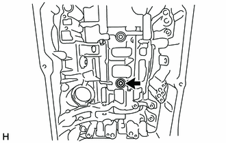
Make sure that the No. 1 brake piston moves smoothly when applying and releasing compressed air (392 kPa, 4.0 kgf/cm2, 57 psi).
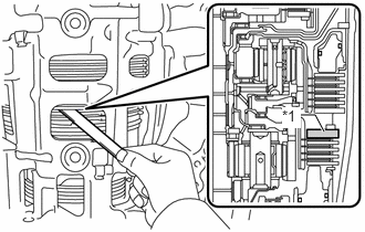
| *1 | Selected No. 1 Brake Flange |
Using a feeler gauge, measure the No. 1 brake pack clearance between the No. 1 brake disc and No. 1 brake flange.
- Standard Clearance:
0.4 to 0.7 mm (0.0158 to 0.0275 in.)
If the clearance is not as specified, select and install an appropriate No. 1 brake flange that will bring the clearance within the specified range.
- No. 1 Brake Flange Thickness:
Mark Thickness (mm (in.)) 0 4.9 (0.193) 1 5.0 (0.197) 2 5.1 (0.201) 3 5.2 (0.205) 4 5.3 (0.209) 5 5.4 (0.213) 6 5.5 (0.217) 7 5.6 (0.220) 8 5.7 (0.224) A 5.8 (0.228)
35678B
25.INSPECT CLEARANCE OF NO. 2 BRAKE
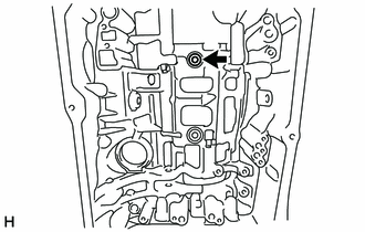
Make sure that the No. 2 brake piston moves smoothly when applying and releasing compressed air (392 kPa, 4.0 kgf/cm2, 57 psi).
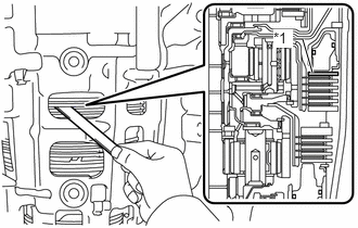
| *1 | Selected No. 2 Brake Flange |
Using a feeler gauge, measure the No. 2 brake pack clearance between the No. 2 brake disc and No. 2 brake flange.
- Standard Clearance:
0.5 to 0.8 mm (0.0197 to 0.0314 in.)
If the clearance is not as specified, select and install an appropriate No. 2 brake flange that will bring the clearance within the specified range.
- No. 2 Brake Flange Thickness:
Mark Thickness (mm (in.)) 0 2.0 (0.0787) 1 2.1 (0.0827) 2 2.2 (0.0866) 3 2.3 (0.0906) 4 2.4 (0.0945) 5 2.5 (0.0984) 6 2.6 (0.102) 7 2.7 (0.106) 8 2.8 (0.110)
35689
26.INSPECT CLEARANCE OF NO. 4 BRAKE
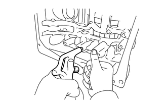
Make sure that the 1st and reverse brake piston moves smoothly when applying and releasing compressed air (392 kPa, 4.0 kgf/cm2, 57 psi).
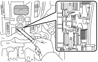
| *1 | Selected No. 4 Brake Flange |
Using a feeler gauge, measure the No. 4 brake pack clearance between the No. 4 brake disc and No. 4 brake flange.
- Standard Clearance:
0.7 to 1.0 mm (0.0276 to 0.0393 in.)
If the clearance is not as specified, select and install an appropriate No. 4 brake flange that will bring the clearance within the specified range.
- No. 4 Brake Flange Thickness:
Mark Thickness (mm (in.)) 0 1.80 (0.0709) 1 1.97 (0.0776) 3 2.11 (0.0831) 4 2.25 (0.0886) 5 2.39 (0.0941) 7 2.53 (0.0996) 8 2.67 (0.105) 10 2.81 (0.111) 11 2.95 (0.116) 12 3.09 (0.122) 14 3.23 (0.127)