HEATING / AIR CONDITIONING VISCOUS HEATER INSTALLATION
PROCEDURE

 87209
1.INSTALL WATER HOSE SUB-ASSEMBLY
87209
1.INSTALL WATER HOSE SUB-ASSEMBLY
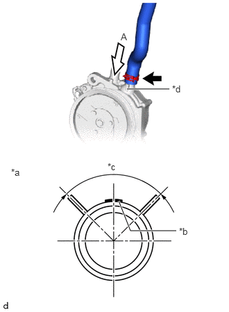
| *a | View A |
| *b | Paint Marking (Yellow) |
| *c | Clip Installation Angle (40°) |
| *d | Rib |
Align the rib of the viscous heater with magnet clutch assembly with the marking (Yellow). Install the water hose sub-assembly (inlet side) and hose clip within the range shown in the illustration.
- NOTICE:
-
Do not apply excessive force to the water hose sub-assembly (inlet side).
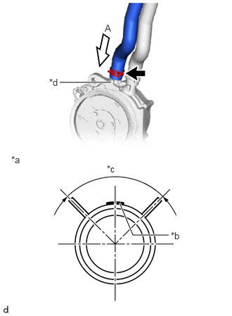
| *a | View A |
| *b | Paint Marking (Orange) |
| *c | Clip Installation Angle (40°) |
| *d | Rib |
Align the rib of the viscous heater with magnet clutch assembly with the marking (orange). Install the water hose sub-assembly (outlet side) and hose clip within the range shown in the illustration.
- NOTICE:
-
Do not apply excessive force to the water hose sub-assembly (outlet side).
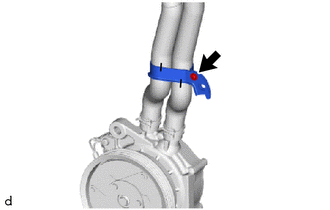
Install the bracket with the screw.
87120G
2.INSTALL VISCOUS HEATER WITH MAGNET CLUTCH ASSEMBLY
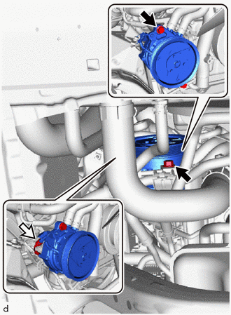

|
Bolt |

|
Connector |
Temporarily install the viscous heater with magnet clutch assembly with the 2 bolts.
Connect the connector.
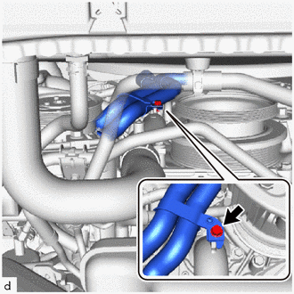
Install the bolt and connect the bracket.
- Torque:
- 9.8 N*m (100 kgf*cm, 87 in.*lbf)
88704
3.CONNECT SUCTION HOSE SUB-ASSEMBLY
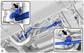
Connect the suction hose sub-assembly with the bolt.
- Torque:
- 9.8 N*m (100 kgf*cm, 87 in.*lbf)
87209
4.CONNECT WATER HOSE SUB-ASSEMBLY
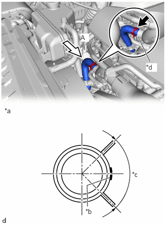
| *a | View A |
| *b | Paint Marking (Blue) |
| *c | Clip Installation Angle (40°) |
| *d | Rib |
Align the rib of the viscous heater with magnet clutch assembly with the marking (blue). Connect the water hose sub-assembly (outletside) and install the hose clip within the range shown in the illustration.
- NOTICE:
-
Do not apply excessive force to the water hose sub-assembly (outletside).
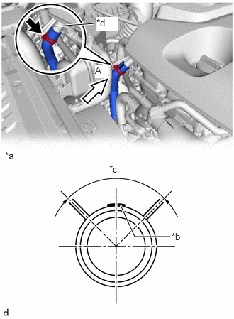
| *a | View A |
| *b | Paint Marking (White) |
| *c | Clip Installation Angle (40°) |
| *d | Positioning Marking |
Align the rib of the viscous heater with magnet clutch assembly with the marking (white). Connect the water hose sub-assembly (inletside) and install the hose clip within the range shown in the illustration.
- NOTICE:
-
Do not apply excessive force to the water hose sub-assembly (inletside).
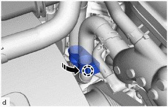

|
Install in this Direction |
Connect each hose and attach the claw to closing the hose clamp.
88359
5.INSTALL VISCOUS HEATER V BELT
6.ADD ENGINE COOLANT
51405A
7.INSTALL NO. 1 ENGINE UNDER COVER SUB-ASSEMBLY