WINDOW / GLASS POWER WINDOW CONTROL SYSTEM TERMINALS OF ECU
CHECK MULTIPLEX NETWORK MASTER SWITCH ASSEMBLY
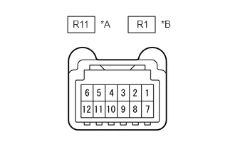
| *A | for LHD |
| *B | for RHD |
Disconnect the R11*1 or R1*2 multiplex network master switch assembly connector.
*1: for LHD
*2: for RHD
Measure the voltage and resistance according to the value(s) in the table below.
- HINT:
-
Measure the values on the wire harness side with the connector disconnected.
| Terminal No. (Symbol) | Wiring Color | Terminal Description | Condition | Specified Condition |
|---|---|---|---|---|
| R11-1 (B) - R11-6 (GND) | P - W-B | Power supply | Always | 11 to 14 V |
| R11-6 (GND) - Body ground | W-B - Body ground | Ground | Always | Below 1 Ω |
| Terminal No. (Symbol) | Wiring Color | Terminal Description | Condition | Specified Condition |
|---|---|---|---|---|
| R1-1 (B) - R1-6 (GND) | P - W-B | Power supply | Always | 11 to 14 V |
| R1-6 (GND) - Body ground | W-B - Body ground | Ground | Always | Below 1 Ω |
Reconnect the R11*1 or R1*2 multiplex network master switch assembly connector.
*1: for LHD
*2: for RHD
Measure the voltage according to the value(s) in the table below.
| Terminal No. (Symbol) | Wiring Color | Terminal Description | Condition | Specified Condition |
|---|---|---|---|---|
| R11-7 (DOWN) - R11-6 (GND) | V - W-B | Power window motor DOWN output | Ignition switch ON, driver door power window regulator switch not pushed or pulled | 11 to 14 V |
| Ignition switch ON, driver door power window moving, driver door power window regulator switch pushed halfway down (Manual operation) | Below 1 V | |||
| R11-3 (UP) - R11-6 (GND) | L - W-B | Power window motor UP output | Ignition switch ON, driver door power window regulator switch not pushed or pulled | 11 to 14 V |
| Ignition switch ON, driver door power window moving, driver door power window regulator switch pulled halfway up (Manual operation) | Below 1 V |
| Terminal No. (Symbol) | Wiring Color | Terminal Description | Condition | Specified Condition |
|---|---|---|---|---|
| R1-7 (DOWN) - R1-6 (GND) | V - W-B | Power window motor DOWN output | Ignition switch ON, driver door power window regulator switch not pushed or pulled | 11 to 14 V |
| Ignition switch ON, driver door power window moving, driver door power window regulator switch pushed halfway down (Manual operation) | Below 1 V | |||
| R1-3 (UP) - R1-6 (GND) | L - W-B | Power window motor UP output | Ignition switch ON, driver door power window regulator switch not pushed or pulled | 11 to 14 V |
| Ignition switch ON, driver door power window moving, driver door power window regulator switch pulled halfway up (Manual operation) | Below 1 V |
Measure the pulse according to the value(s) in the table below.
| Terminal No. (Symbol) | Wiring Color | Terminal Description | Condition | Specified Condition |
|---|---|---|---|---|
| R11-5 (LIN1) - Body ground | GR - Body ground | LIN communication line | Ignition switch ON | Pulse generation |
| R11-11 (LIN2) - Body ground | P - Body ground | LIN communication line | Ignition switch ON | Pulse generation |
| Terminal No. (Symbol) | Wiring Color | Terminal Description | Condition | Specified Condition |
|---|---|---|---|---|
| R1-5 (LIN1) - Body ground | W - Body ground | LIN communication line | Ignition switch ON | Pulse generation |
| R1-11 (LIN2) - Body ground | P - Body ground | LIN communication line | Ignition switch ON | Pulse generation |
CHECK POWER WINDOW REGULATOR MOTOR ASSEMBLY LH
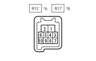
| *A | for LHD |
| *B | for RHD |
Disconnect the R12*1 or R17*2 power window regulator motor assembly LH connector.
*1: for LHD
*2: for RHD
Measure the voltage and resistance according to the value(s) in the table below.
- HINT:
-
Measure the values on the wire harness side with the connector disconnected.
| Terminal No. (Symbol) | Wiring Color | Terminal Description | Condition | Specified Condition |
|---|---|---|---|---|
| R12-1 (GND) - Body ground | W-B - Body ground | Ground | Always | Below 1 Ω |
| R12-2 (B) - Body ground | L - Body ground | Power supply | Always | 11 to 14 V |
| Terminal No. (Symbol) | Wiring Color | Terminal Description | Condition | Specified Condition |
|---|---|---|---|---|
| R17-1 (GND) - Body ground | W-B - Body ground | Ground | Always | Below 1 Ω |
| R17-2 (B) - Body ground | R - Body ground | Power supply | Always | 11 to 14 V |
Reconnect the R12*1 or R17*2 power window regulator motor assembly LH connector.
*1: for LHD
*2: for RHD
Measure the voltage according to the value(s) in the table below.
| Terminal No. (Symbol) | Wiring Color | Terminal Description | Condition | Specified Condition |
|---|---|---|---|---|
| R12-7 (DOWN) - R12-1 (GND) | V - W-B | Power window motor DOWN input | Ignition switch ON, multiplex network master switch assembly (driver door power window regulator switch) not pushed or pulled | 11 to 14 V |
| Ignition switch ON, driver door power window moving, multiplex network master switch assembly (driver door power window regulator switch) pushed halfway down (Manual operation) | Below 1 V | |||
| Ignition switch ON, driver door power window fully closed | 11 to 14 V | |||
| Ignition switch ON, driver door power window moving, multiplex network master switch assembly (driver door power window regulator switch) fully pushed down (Auto operation) | Below 1 V | |||
| Ignition switch ON, driver door power window fully open | 11 to 14 V | |||
| R12-10 (UP) - R12-1 (GND) | L - W-B | Power window motor UP input | Ignition switch ON, multiplex network master switch assembly (driver door power window regulator switch) not pushed or pulled | 11 to 14 V |
| Ignition switch ON, driver door power window moving, multiplex network master switch assembly (driver door power window regulator switch) pulled halfway up (Manual operation) | Below 1 V | |||
| Ignition switch ON, driver door power window fully opened | 11 to 14 V | |||
| Ignition switch ON, driver door power window moving, multiplex network master switch assembly (driver door power window regulator switch) fully pulled up (Auto operation) | Below 1 V | |||
| Ignition switch ON, driver door power window fully closed | 11 to 14 V |
| Terminal No. (Symbol) | Wiring Color | Terminal Description | Condition | Specified Condition |
|---|---|---|---|---|
| R17-4 (AUTO) - R17-1 (GND) | R - W-B | Power window motor AUTO UP input | Ignition switch ON, power window regulator switch assembly not pushed or pulled | 11 to 14 V |
| Ignition switch ON, front passenger door power window moving, power window regulator switch assembly pushed halfway down (Manual operation) | Below 1 V | |||
| Ignition switch ON, front passenger door power window fully closed | 11 to 14 V | |||
| Ignition switch ON, front passenger door power window moving, power window regulator switch assembly fully pushed down (Auto operation) | Below 1 V | |||
| Ignition switch ON, front passenger door power window fully open | 11 to 14 V | |||
| Power window motor AUTO DOWN input | Ignition switch ON, front passenger door power window fully closed | 11 to 14 V | ||
| Ignition switch ON, front passenger door power window moving, power window regulator switch assembly fully pushed down (Auto operation) | Below 1 V | |||
| Ignition switch ON, front passenger door power window fully open | 11 to 14 V | |||
| R17-7 (DOWN) - R17-1 (GND) | V - W-B | Power window motor DOWN input | Ignition switch ON, power window regulator switch assembly not pushed or pulled | 11 to 14 V |
| Ignition switch ON, front passenger door power window moving, power window regulator switch assembly pushed halfway down (Manual operation) | Below 1 V | |||
| Ignition switch ON, front passenger door power window fully closed | 11 to 14 V | |||
| Ignition switch ON, front passenger door power window moving, power window regulator switch assembly fully pushed down (Auto operation) | Below 1 V | |||
| Ignition switch ON, front passenger door power window fully open | 11 to 14 V | |||
| R17-10 (UP) - R17-1 (GND) | L - W-B | Power window motor UP input | Ignition switch ON, power window regulator switch assembly not pushed or pulled | 11 to 14 V |
| Ignition switch ON, front passenger door power window moving, power window regulator switch assembly pulled halfway up (Manual operation) | Below 1 V | |||
| Ignition switch ON, front passenger door power window fully open | 11 to 14 V | |||
| Ignition switch ON, front passenger door power window moving, power window regulator switch assembly fully pulled up (Auto operation) | Below 1 V | |||
| Ignition switch ON, front passenger door power window fully closed | 11 to 14 V |
Measure the pulse according to the value(s) in the table below.
| Terminal No. (Symbol) | Wiring Color | Terminal Description | Condition | Specified Condition |
|---|---|---|---|---|
| R12-9 (LIN) - Body ground | P - Body ground | LIN communication line | Ignition switch ON | Pulse generation |
| Terminal No. (Symbol) | Wiring Color | Terminal Description | Condition | Specified Condition |
|---|---|---|---|---|
| R17-9 (LIN) - Body ground | G - Body ground | LIN communication line | Ignition switch ON | Pulse generation |
CHECK POWER WINDOW REGULATOR MOTOR ASSEMBLY RH
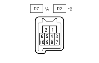
| *A | for LHD |
| *B | for RHD |
Disconnect the R7*1 or R2*2 power window regulator motor assembly RH connector.
*1: for LHD
*2: for RHD
Measure the voltage and resistance according to the value(s) in the table below.
- HINT:
-
Measure the values on the wire harness side with the connector disconnected.
| Terminal No. (Symbol) | Wiring Color | Terminal Description | Condition | Specified Condition |
|---|---|---|---|---|
| R7-1 (GND) - Body ground | W-B - Body ground | Ground | Always | Below 1 Ω |
| R7-2 (B) - Body ground | R - Body ground | Power supply | Always | 11 to 14 V |
| Terminal No. (Symbol) | Wiring Color | Terminal Description | Condition | Specified Condition |
|---|---|---|---|---|
| R2-1 (GND) - Body ground | W-B - Body ground | Ground | Always | Below 1 Ω |
| R2-2 (B) - Body ground | L - Body ground | Power supply | Always | 11 to 14 V |
Reconnect the R7*1 or R2*2 power window regulator motor assembly RH connector.
*1: for LHD
*2: for RHD
Measure the voltage according to the value(s) in the table below.
| Terminal No. (Symbol) | Wiring Color | Terminal Description | Condition | Specified Condition |
|---|---|---|---|---|
| R7-4 (AUTO) - R7-1 (GND) | R - W-B | Power window motor AUTO UP input | Ignition switch ON, front passenger door power window fully open | 11 to 14 V |
| Ignition switch ON, front passenger door power window moving, power window regulator switch assembly fully pulled up (Auto operation) | Below 1 V | |||
| Ignition switch ON, front passenger door power window fully closed | 11 to 14 V | |||
| Power window motor AUTO DOWN input | Ignition switch ON, front passenger door power window fully closed | 11 to 14 V | ||
| Ignition switch ON, front passenger door power window moving, power window regulator switch assembly fully pushed down (Auto operation) | Below 1 V | |||
| Ignition switch ON, front passenger door power window fully open | 11 to 14 V | |||
| R7-7 (DOWN) - R7-1 (GND) | V - W-B | Power window motor DOWN input | Ignition switch ON, power window regulator switch assembly not pushed or pulled | 11 to 14 V |
| Ignition switch ON, front passenger door power window moving, power window regulator switch assembly pushed halfway down (Manual operation) | Below 1 V | |||
| Ignition switch ON, front passenger door power window fully closed | 11 to 14 V | |||
| Ignition switch ON, front passenger door power window moving, power window regulator switch assembly fully pushed down (Auto operation) | Below 1 V | |||
| Ignition switch ON, front passenger door power window fully open | 11 to 14 V | |||
| R7-10 (UP) - R7-1 (GND) | L - W-B | Power window motor UP input | Ignition switch ON, power window regulator switch assembly not pushed or pulled | 11 to 14 V |
| Ignition switch ON, front passenger door power window moving, power window regulator switch assembly pulled halfway up (Manual operation) | Below 1 V | |||
| Ignition switch ON, front passenger door power window fully open | 11 to 14 V | |||
| Ignition switch ON, front passenger door power window moving, power window regulator switch assembly fully pulled up (Auto operation) | Below 1 V | |||
| Ignition switch ON, front passenger door power window fully closed | 11 to 14 V |
| Terminal No. (Symbol) | Wiring Color | Terminal Description | Condition | Specified Condition |
|---|---|---|---|---|
| R2-7 (DOWN) - R2-1 (GND) | V - W-B | Power window motor DOWN input | Ignition switch ON, multiplex network master switch assembly (driver door power window regulator switch) not pushed or pulled | 11 to 14 V |
| Ignition switch ON, driver door power window moving, multiplex network master switch assembly (driver door power window regulator switch) pushed halfway down (Manual operation) | Below 1 V | |||
| Ignition switch ON, driver door power window fully closed | 11 to 14 V | |||
| Ignition switch ON, driver door power window moving, multiplex network master switch assembly (driver door power window regulator switch) fully pushed down (Auto operation) | Below 1 V | |||
| Ignition switch ON, driver door power window fully open | 11 to 14 V | |||
| R2-10 (UP) - R2-1 (GND) | L - W-B | Power window motor UP input | Ignition switch ON, multiplex network master switch assembly (driver door power window regulator switch) not pushed or pulled | 11 to 14 V |
| Ignition switch ON, driver door power window moving, multiplex network master switch assembly (driver door power window regulator switch) pulled halfway up (Manual operation) | Below 1 V | |||
| Ignition switch ON, multiplex network master switch assembly (driver door power window regulator switch) fully open | 11 to 14 V | |||
| Ignition switch ON, driver door power window moving, multiplex network master switch assembly (driver door power window regulator switch) fully pulled up (Auto operation) | Below 1 V | |||
| Ignition switch ON, driver door power window fully closed | 11 to 14 V |
Measure the pulse according to the value(s) in the table below.
| Terminal No. (Symbol) | Wiring Color | Terminal Description | Condition | Specified Condition |
|---|---|---|---|---|
| R7-9 (LIN) - Body ground | G - Body ground | LIN communication line | Ignition switch ON | Pulse generation |
| Terminal No. (Symbol) | Wiring Color | Terminal Description | Condition | Specified Condition |
|---|---|---|---|---|
| R2-9 (LIN) - Body ground | P - Body ground | LIN communication line | Ignition switch ON | Pulse generation |
CHECK INSTRUMENT PANEL JUNCTION BLOCK ASSEMBLY AND MAIN BODY ECU (MULTIPLEX NETWORK BODY ECU)
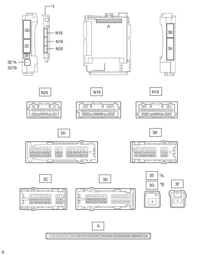
| *A | for LHD | *B | for RHD |
| *1 | Main Body ECU (Multiplex Network Body ECU) | - | - |
Measure the voltage and waveform according to the value(s) in the table below.
| Terminal No. (Symbol) | Wiring Color | Terminal Description | Condition | Specified Condition |
|---|---|---|---|---|
| N19-1 (FLCY) - Body ground | R - Body ground | Front door courtesy light switch assembly LH input | Front door courtesy light switch assembly LH open | Below 1 V |
| Front door courtesy light switch assembly LH closed | 4.7 to 5.3 V | |||
| N20-18 (L2) - Body ground | W - Body ground | Driver door key-linked lock input | Driver door key cylinder turned to lock | Below 1 V |
| Driver door key cylinder off | Pulse generation | |||
| N20-17 (UL3) - Body ground | Y - Body ground | Driver door key-linked unlock input | Driver door key cylinder turned to unlock | Below 1 V |
| Driver door key cylinder off | Pulse generation | |||
| 3B-17 (LIN2) - Body ground | G- Body ground | LIN communication line | Ignition switch ON | Pulse generation |
| Terminal No. (Symbol) | Wiring Color | Terminal Description | Condition | Specified Condition |
|---|---|---|---|---|
| N19-6 (FRCY) - Body ground | R - Body ground | Front door courtesy light switch assembly RH input | Front door courtesy light switch assembly RH open | Below 1 V |
| Front door courtesy light switch assembly RH closed | 4.7 to 5.3 V | |||
| N20-18 (L2) - Body ground | W - Body ground | Driver door key-linked lock input | Driver door key cylinder turned to lock | Below 1 V |
| Driver door key cylinder off | Pulse generation | |||
| N20-17 (UL3) - Body ground | Y - Body ground | Driver door key-linked unlock input | Driver door key cylinder turned to unlock | Below 1 V |
| Driver door key cylinder off | Pulse generation | |||
| 3B-17 (LIN2) - Body ground | G - Body ground | LIN communication line | Ignition switch ON | Pulse generation |