RM35X0E
_59
Vehicle Exterior
_079256
LIGHTING (EXT)
_0384446
AUTOMATIC LIGHT CONTROL SENSOR
G
LIGHTING (EXT) AUTOMATIC LIGHT CONTROL SENSOR ON-VEHICLE INSPECTION
PROCEDURE

 89120A
1.INSPECT AUTOMATIC LIGHT CONTROL SENSOR
89120A
1.INSPECT AUTOMATIC LIGHT CONTROL SENSOR
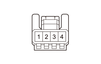
a.
1.51,0.198 1.885,0.417
0.375,0.219
0.823,1.26 1.24,1.26
true
1.385,1.854 1.542,1.354
true
0.135,0.104 0.344,0.26
0.208,0.156
10
false
*a
1.615,0.219 2.042,0.625
0.427,0.406
10
false
Q2
0.417,1.156 0.823,1.323
0.406,0.167
10
false
CLTB
1.198,1.875 1.604,2.042
0.406,0.167
10
false
CLTE
| *a | Front view of wire harness connector
(to Automatic Light Control Sensor) |
Disconnect the automatic light control sensor connector.
b.
Measure the voltage and resistance according to the value(s) in the table below.
- Standard Voltage:
Tester Connection Condition Specified Condition Q2-1 (CLTB) - Q2-2 (CLTE) Ignition switch off Below 1 V Ignition switch on (IG) 11 to 14 V
- Standard Resistance:
Tester Connection Condition Specified Condition Q2-2 (CLTE) - Body ground Always Below 1 Ω
If the result is not as specified, repair or replace the wire harness or connector.
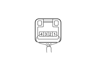
c.
1.542,0.24 1.917,0.479
0.375,0.24
1.833,1.177 2.385,0.885
true
1.458,1.167 0.896,0.896
true
0.188,0.135 0.438,0.313
0.25,0.177
10
false
*a
1.635,0.281 1.927,0.667
0.292,0.385
10
false
Q2
0.542,0.771 0.958,0.948
0.417,0.177
10
false
CLTS
2.438,0.792 2.833,0.958
0.396,0.167
10
false
CLTE
| *a | Component with harness connected
(Automatic Light Control Sensor) |
Reconnect the automatic light control sensor connector.
d.
Connect an oscilloscope to the automatic light control sensor connector.
e.
2.844,1.646 3.219,1.813
0.375,0.167
10
false
GND
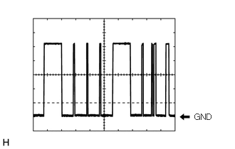
Check the waveform.
- OK:
Tester Connection Tool Setting Condition Specified Condition If the result is not as specified, replace the automatic light control sensor.
Q2-4 (CLTS) - Q2-2 (CLTE) 2 V/DIV., 10 ms./DIV. Ignition switch on (IG), light control switch in AUTO position Correct waveform is as shown
- HINT:
-
The communication waveform changes according to the surrounding brightness.