RM35X0E
_59
Vehicle Exterior
_079256
LIGHTING (EXT)
_0384443
HAZARD WARNING SWITCH
G
LIGHTING (EXT) HAZARD WARNING SWITCH INSPECTION
PROCEDURE

 84330
1.INSPECT HAZARD WARNING SIGNAL SWITCH ASSEMBLY
84330
1.INSPECT HAZARD WARNING SIGNAL SWITCH ASSEMBLY
a.
0.094,0.083 0.406,0.24
0.313,0.156
10
false
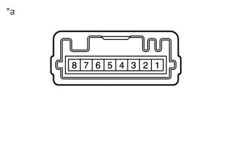
*a
| *a | Component without harness connected
(Hazard Warning Signal Switch Assembly) |
Inspect the hazard warning signal switch.
i.
Measure the resistance according to the value(s) in the table below.
- Standard Resistance:
Tester Connection Switch Condition Specified Condition If the result is not as specified, replace the hazard warning signal switch assembly.
5 - 4 Hazard warning signal switch off 10 kΩ or higher Hazard warning signal switch on Below 1 Ω
b.

1.24,1.604 1.448,1.021
true
2.094,1.625 1.979,1
true
0.094,0.083 0.406,0.24
0.313,0.156
10
false
*a
1.104,1.646 1.563,1.844
0.458,0.198
10
false
ILL+
2.052,1.667 2.51,1.865
0.458,0.198
10
false
ILL-
| *a | Component without harness connected
(Hazard Warning Signal Switch Assembly) |
Check the illumination.
i.
Apply battery voltage to the connector and check the illumination conditions.
- OK:
Battery Connection Specified Condition If the result is not as specified, replace the hazard warning signal switch assembly.
Battery positive (+) → 6 (ILL+)
Battery negative (-) → 3 (ILL-)Illuminates