DRIVE SHAFT / PROPELLER SHAFT PROPELLER SHAFT ASSEMBLY(for Standard Roof) REASSEMBLY
CAUTION / NOTICE / HINT
- NOTICE:
- ·
When using a vise, place aluminum plates between the part and vise.
·When using a vise, do not overtighten it.
CAUTION / NOTICE / HINT
PROCEDURE

 37230
1.INSTALL CENTER NO. 1 SUPPORT BEARING ASSEMBLY
37230
1.INSTALL CENTER NO. 1 SUPPORT BEARING ASSEMBLY
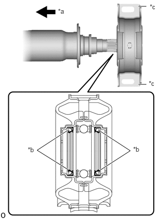
| *a | Front Side |
| *b | Seal |
| *c | Cutout |
Install the center No. 1 support bearing assembly to the intermediate shaft.
- NOTICE:
- ·
Carefully insert the part so that the seal does not invert.
·Make sure to install the part so that the cutouts face the rear of the vehicle.
Install the 2 washers.
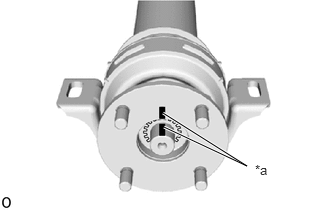
| *a | Matchmark |
Align the matchmarks on the flange coupling and intermediate shaft, and then install the flange coupling to the intermediate shaft.
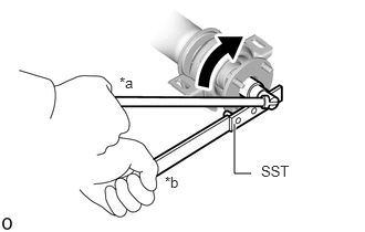
| *a | Turn |
| *b | Hold |
Using SST to hold the flange coupling, install a new lock nut.
- SST
- 09330-00021
- Torque:
- 101.5 N*m (1035 kgf*cm, 75 ft.*lbf)
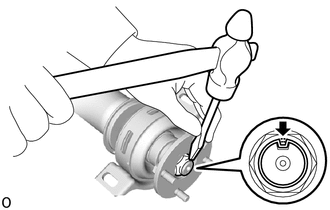
Using a chisel and hammer, stake the lock nut.
- NOTICE:
- ·
Fully stake the lock nut along the entire groove.
·Do not damage the threads of the intermediate shaft.
2.INSTALL SPIDER BEARING
- HINT:
-
Use the same procedure for all spiders.
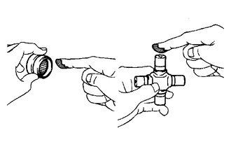
Apply grease to a new spider and new spider bearings.
- Grease:
Lithium base chassis grease NLGI No. 2
- NOTICE:
-
Do not apply too much grease.
Install the spider to the flange yoke.
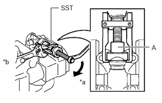
| *a | Turn |
| *b | Hold |
Using SST, install 2 of the spider bearings to the spider.
- SST
- 09332-25010
- HINT:
-
Before installing SST, sufficiently raise the part labeled A. If the part labeled A is too low, it may be difficult to install SST.
Using SST, adjust both spider bearings so that the snap ring grooves are as wide as possible and equal in width.
- SST
- 09332-25010
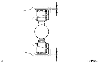
Install 2 new snap rings to the installed spider bearings. The snap rings must have equal thickness and allow 0 to 0.05 mm (0 to 0.00196 in.) of axial play.
- NOTICE:
-
While the installed snap rings should have equal thickness, if the axial play is greater than 0.05 mm (0.00196 in.), select 2 snap rings that have as close to the same thickness as possible.
- HINT:
-
Do not reuse the snap rings.
- Standard Snap Ring Thickness:
Part No. Thickness 90520-29039 1.98 to 2.00 mm (0.0780 to 0.0787 in.) 90520-29040 2.00 to 2.02 mm (0.0788 to 0.0795 in.) 90520-29041 2.02 to 2.04 mm (0.0796 to 0.0803 in.) 90520-29042 2.04 to 2.06 mm (0.0804 to 0.0811 in.) 90520-29043 2.06 to 2.08 mm (0.0812 to 0.0818 in.) 90520-29044 2.08 to 2.10 mm (0.0819 to 0.0826 in.) 90520-29045 2.10 to 2.12 mm (0.0827 to 0.0834 in.) 90520-29046 2.12 to 2.14 mm (0.0835 to 0.0842 in.) 90520-29047 2.14 to 2.16 mm (0.0843 to 0.0850 in.) 90520-29048 2.16 to 2.18 mm (0.0851 to 0.0858 in.)
- NOTICE:
- ·
While the installed snap rings should have equal thickness, if the axial play is greater than 0.05 mm (0.00196 in.), select 2 snap rings that have as close to the same thickness as possible.
·Use a new snap ring.
·Use a snap ring with as close to the same thickness as possible on both ends.
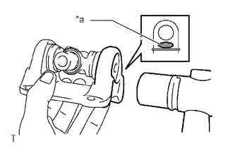
| *a | Hammering Point |
Using a hammer, tap the flange yoke until there is no clearance between the spider bearing outer race and snap ring.
- HINT:
-
Install the spider bearing on the sleeve side using the procedure described above.
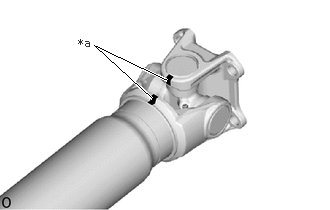
| *a | Matchmark |
Align the matchmarks on the flange yoke and propeller shaft.
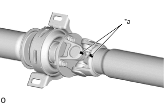
| *a | Matchmark |
Align the matchmarks on the flange yoke and propeller shaft.
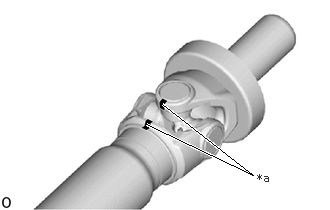
| *a | Matchmark |
Align the matchmarks on the sleeve yoke and intermediate shaft.
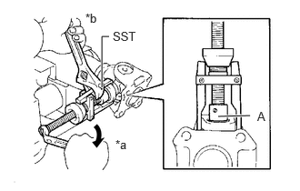
| *a | Turn |
| *b | Hold |
Using SST, install the 2 spider bearings to the spider.
- SST
- 09332-25010
- HINT:
-
Before installing SST, sufficiently raise the part labeled A. If the part labeled A is too low, it may be difficult to install SST.
Using SST, adjust both spider bearings so that the front propeller shaft joint spider bearing snap ring grooves are as wide as possible and equal in width.
- SST
- 09332-25010
Install 2 new snap rings to the installed spider bearings. The snap rings must have equal thickness and allow 0 to 0.05 mm (0 to 0.00196 in.) of axial play.
- NOTICE:
-
While the installed snap rings should have equal thickness, if the axial play is greater than 0.05 mm (0.00196 in.), select 2 snap rings that have as close to the same thickness as possible.
- HINT:
-
Do not reuse the snap rings.
- Standard Snap Ring Thickness:
Part No. Thickness 90520-29039 1.98 to 2.00 mm (0.0780 to 0.0787 in.) 90520-29040 2.00 to 2.02 mm (0.0788 to 0.0795 in.) 90520-29041 2.02 to 2.04 mm (0.0796 to 0.0803 in.) 90520-29042 2.04 to 2.06 mm (0.0804 to 0.0811 in.) 90520-29043 2.06 to 2.08 mm (0.0812 to 0.0818 in.) 90520-29044 2.08 to 2.10 mm (0.0819 to 0.0826 in.) 90520-29045 2.10 to 2.12 mm (0.0827 to 0.0834 in.) 90520-29046 2.12 to 2.14 mm (0.0835 to 0.0842 in.) 90520-29047 2.14 to 2.16 mm (0.0843 to 0.0850 in.) 90520-29048 2.16 to 2.18 mm (0.0851 to 0.0858 in.)
- NOTICE:
- ·
While the installed snap rings should have equal thickness, if the axial play is greater than 0.05 mm (0.00196 in.), select 2 snap rings that have as close to the same thickness as possible.
·Use a new snap ring.
·Use a snap ring with as close to the same thickness as possible on both ends.
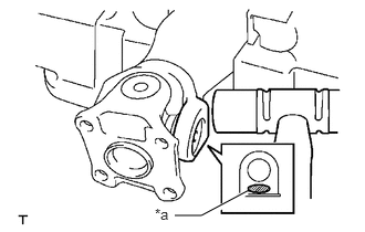
| *a | Hammering Point |
Using a hammer, tap the propeller shaft until there is no clearance between the spider bearing outer race and snap ring.
- HINT:
-
Install the spider bearing on the sleeve side using the procedure described above.
Completely remove any oil, etc. and clean the contact surfaces of the flange coupling and flange yoke.
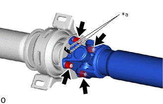
| *a | Matchmark |
Align the matchmarks on the flange yoke and flange coupling, and connect them with the 4 washers and 4 nuts.
- Torque:
- 88.2 N*m (899 kgf*cm, 65 ft.*lbf)
- NOTICE:
-
If any parts with matchmarks are replaced during inspection, reassemble them so that the sleeve yoke of the intermediate shaft and the rear flange yoke of the propeller shaft are at right angles to each other.
3.INSPECT PROPELLER SHAFT GREASE FITTING DIRECTION (w/ Grease fittings)
- HINT:
- ·
When replacing a spider bearing, be sure that the grease fitting hole is facing the direction shown in the illustration.
·Fill the grease fittings with grease.
- Grease:
Lithium base chassis grease NLGI No. 2
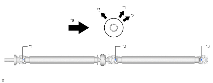
| *1 | No. 1 Grease Fitting | *2 | No. 2 Grease Fitting |
| *3 | No. 3 Grease Fitting | - | - |
| *a | Rear Side | - | - |