DRIVE SHAFT / PROPELLER SHAFT PROPELLER SHAFT ASSEMBLY(for High Roof) DISASSEMBLY
CAUTION / NOTICE / HINT
- NOTICE:
- ·
When using a vise, place aluminum plates between the part and vise.
·When using a vise, do not overtighten it.
PROCEDURE

 1.REMOVE SPIDER BEARING
- HINT:
-
Use the same procedure for all spiders.
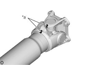
| *a | Matchmark |
Place matchmarks on the flange yoke (rear side) and No. 2 propeller shaft.
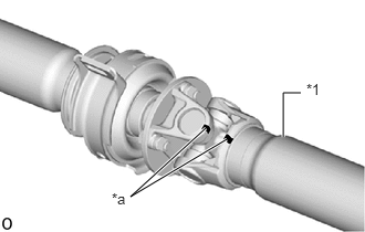
| *1 | No. 2 Propeller Shaft |
| *a | Matchmark |
Place matchmarks on the flange yoke (center side) and No. 2 propeller shaft.
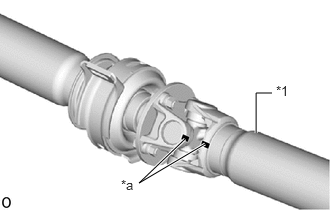
| *1 | No. 1 Propeller Shaft |
| *a | Matchmark |
Place matchmarks on the flange yoke and No. 1 propeller shaft.
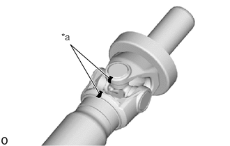
| *a | Matchmark |
Place matchmarks on the sleeve yoke and intermediate shaft.
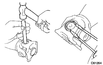
Using a brass bar and hammer, slightly tap in the spider bearing outer races.
Using 2 screwdrivers, remove the 4 snap rings from the grooves.
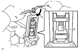
| *a | Turn |
| *b | Hold |
Using SST, push out the spider bearing from the propeller shaft assembly.
- SST
- 09332-25010
- HINT:
-
Before installing SST, sufficiently raise the part labeled A. If the part labeled A is too low, it may be difficult to install SST.
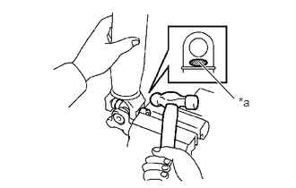
| *a | Hammering Point |
Tap off the propeller shaft to remove the spider bearing.
- NOTICE:
-
Do not tap the shaft.
- HINT:
-
Remove the spider bearing on the opposite side using the same procedure.
Remove the flange yoke from the propeller shaft.
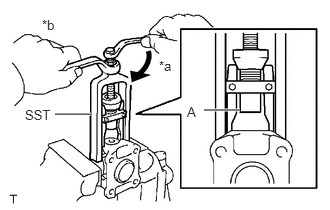
| *a | Turn |
| *b | Hold |
Install the 2 removed spider bearing outer races to the spider.
Using SST, push out the spider bearing from the flange yoke.
- SST
- 09332-25010
- HINT:
-
Before installing SST, sufficiently raise the part labeled A. If the part labeled A is too low, it may be difficult to install SST.
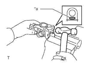
| *a | Hammering Point |
Tap off the spider bearing with a hammer.
Remove the spider.
37230
2.REMOVE CENTER NO. 1 SUPPORT BEARING ASSEMBLY
- HINT:
-
Use the same procedure all center bearing.
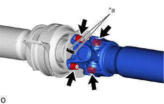
| *a | Matchmark |
Place matchmarks on the flange coupling and flange yoke.
Remove the 4 nuts and 4 washers.
Remove the propeller shaft.

Using a chisel and hammer, loosen the staked part of the lock nut.
- SST
- 09930-00010 (09931-00010, 09931-00020)
- NOTICE:
- ·
Completely loosen the staked part of the lock nut when removing it.
·Do not damage the threads of the intermediate shaft.
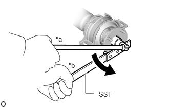
| *a | Turn |
| *b | Hold |
Using SST and a 30 mm deep socket wrench, remove the lock nut.
- SST
- 09330-00021
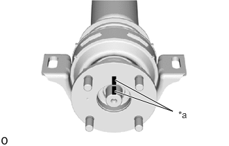
| *a | Matchmark |
Place matchmarks on the intermediate shaft and flange coupling.
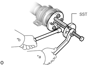
| *a | Turn |
| *b | Hold |
Using SST, remove the flange coupling and 2 washers from the intermediate shaft.
- SST
- 09950-30012 (09951-03010, 09953-03010, 09954-03010, 09955-03030, 09956-03030)
Remove the center No. 1 support bearing assembly.