CRUISE CONTROL CRUISE CONTROL SYSTEM TERMINALS OF ECM
CHECK ECM (for 1GD-FTV)
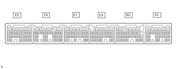
- HINT:
-
The standard voltage, resistance and waveform between each pair of the ECM terminals are shown in the table below. The appropriate conditions for checking each pair of the terminals is also indicated. The result of checks should be compared with the standard voltage, resistance and waveform for each pair of the terminals as displayed in the Specified Condition column. The illustration above can be used as a reference to identify the ECM terminal locations.
| Terminal No. (Symbol) | Wiring Color | Terminal Description | Condition | Specified Condition |
|---|---|---|---|---|
| A2-13 (STP) - A2-5 (E1) | V - W-B | Stop light switch signal | Brake pedal depressed | 7.5 to 14 V |
| Brake pedal released | Below 1.5 V | |||
| A2-12 (ST1-) - A2-5 (E1) | B - W-B | Stop light switch signal | Ignition switch to ON, brake pedal depressed | Below 1.5 V |
| Ignition switch to ON, brake pedal released | 7.5 to 14 V | |||
| A2-26 (CCS) - Body ground | B - Body ground | Steering pad switch circuit | Cruise control switch not pushed | 1 MΩ or higher |
| Cruise control main switch pushed | Below 2.5 Ω | |||
| CANCEL switch pushed | 228 to 252 Ω | |||
| +RES switch pushed | 599 to 661 Ω | |||
| -SET switch pushed | 1463 to 1617 Ω |
CHECK ECM (for 7GR-FKS)
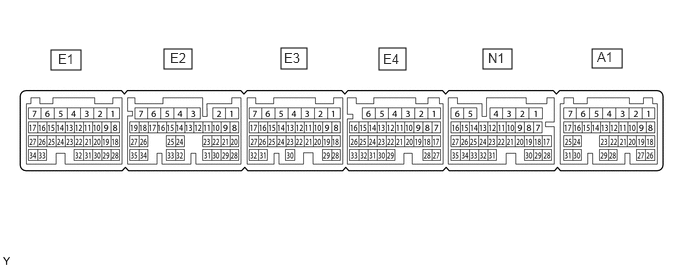
- HINT:
-
The standard voltage, resistance and waveform between each pair of the ECM terminals are shown in the table below. The appropriate conditions for checking each pair of the terminals is also indicated. The result of checks should be compared with the standard voltage, resistance and waveform for each pair of the terminals as displayed in the Specified Condition column. The illustration above can be used as a reference to identify the ECM terminal locations.
| Terminal No. (Symbol) | Wiring Color | Terminal Description | Condition | Specified Condition |
|---|---|---|---|---|
| N1-16 (STP) - E3-1 (E1) | W - W-B | Stop light switch signal | Brake pedal depressed | 7.5 to 14 V |
| Brake pedal released | Below 1.5 V | |||
| N1-15 (ST1-) - E3-1 (E1) | B - W-B | Stop light switch signal | Ignition switch to ON, brake pedal depressed | 0 to 1.5 V |
| Ignition switch to ON, brake pedal released | 7.5 to 14 V | |||
| N1-17 (CCS) - Body ground | B - Body ground | Steering pad switch circuit | Cruise control switch not pushed | 1 MΩ or higher |
| Cruise control main switch pushed | Below 2.5 Ω | |||
| CANCEL switch pushed | 228 to 252 Ω | |||
| +RES switch pushed | 599 to 661 Ω | |||
| -SET switch pushed | 1463 to 1617 Ω |