BRAKE CONTROL / DYNAMIC CONTROL SYSTEMS ELECTRONICALLY CONTROLLED BRAKE SYSTEM(w/o VSC OFF Switch) C137BA2 Brake System Control Module "A" System Voltage System Voltage Low
DESCRIPTION
If a malfunction is detected in the power supply circuit, the skid control ECU (brake actuator assembly) stores this DTC and the fail-safe function prohibits ABS operation.
This DTC is stored when the +BS terminal voltage meets one of the DTC detection conditions due to a malfunction in the power supply or charging circuit such as the battery or alternator circuit, etc.
The DTC is cleared when the +BS terminal voltage returns to normal.
| DTC No. | Detection Item | DTC Detection Condition | Trouble Area |
|---|---|---|---|
| C137BA2 | Brake System Control Module "A" System Voltage System Voltage Low | Any of the following is detected:
1.
The vehicle speed is 6 km/h (4 mph) or more and the +BS terminal voltage (soft low voltage) is less than 9.6 V for 1 second or more. 2.
The vehicle speed is 6 km/h (4 mph) or more and the +BS terminal voltage (hard low voltage) is less than 6.9 V for 1 second or more. 3.
The +BS terminal voltage is less than 6.7 V and the skid control ECU (brake actuator assembly) judges that power supply voltage is abnormal for 0.06 seconds or more. 4.
The vehicle speed is 15 km/h (9 mph) or more and the +BS terminal voltage is 9.6 V or more, the skid control ECU (brake actuator assembly) turns on more than one valve at the same time within a short period of time and the valve relay supply voltage drop exceeds the threshold.* 5.
When the system has started, the +BS terminal voltage is less than 5 V for 0.5 seconds or more. 6.
The +BS terminal voltage is less than 2.6 V for 0.2 seconds or more. |
·
Battery ·
Charging system ·
Internal power supply circuit of the skid control ECU (brake actuator assembly) |
*: The skid control ECU (brake actuator assembly) monitors the resistance of the power source line at the +BS terminal. A malfunction is detected when an abnormality occurs in the +BS terminal wire harness or its connection and the skid control ECU (brake actuator assembly) determines that the wiring resistance at the +BS terminal exceeds the standard resistance.
| Vehicle Condition | |||||||
|---|---|---|---|---|---|---|---|
| Pattern 1 | Pattern 2 | Pattern 3 | Pattern 4 | Pattern 5 | Pattern 6 | ||
| Diagnosis Condition | The vehicle speed is 6 km/h (4 mph) or more. | ○ | ○ | - | - | - | - |
| The vehicle speed is 15 km/h (9 mph) or more and the +BS terminal voltage is 9.6 V or more. | - | - | - | ○ | - | - | |
| The system has started. | - | - | - | - | ○ | - | |
| Malfunction Status | The +BS terminal voltage (soft low voltage) is less than 9.6 V. | ○ | - | - | - | - | - |
| The +BS terminal voltage (hard low voltage) is less than 6.9 V. | - | ○ | - | - | - | - | |
| The +BS terminal voltage is less than 6.7 V and the skid control ECU (brake actuator assembly) judges that power supply voltage is abnormal. | - | - | ○ | - | - | - | |
| The skid control ECU (brake actuator assembly) turns on more than one valve at the same time within a short period of time and the valve relay supply voltage drop exceeds the threshold.* | - | - | - | ○ | - | - | |
| The +BS terminal voltage is less than 5 V. | - | - | - | - | ○ | - | |
| The +BS terminal voltage is less than 2.6 V. | - | - | - | - | - | ○ | |
| Detection Time | 1 second or more. | 1 second or more. | 0.06 seconds or more. | - | 0.5 seconds or more. | 0.2 seconds or more. | |
| Number of Trips | 1 trip | 1 trip | 1 trip | 1 trip | 1 trip | 1 trip | |
*: The skid control ECU (brake actuator assembly) monitors the resistance of the power source line at the +BS terminal. A malfunction is detected when an abnormality occurs in the +BS terminal wire harness or its connection and the skid control ECU (brake actuator assembly) determines that the wiring resistance at the +BS terminal exceeds the standard resistance.
- HINT:
-
DTC will be output when conditions for either of the patterns in the table above are met.
WIRING DIAGRAM
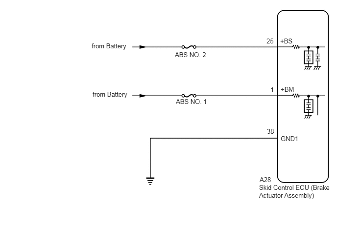
CAUTION / NOTICE / HINT
- NOTICE:
- ·
Inspect the fuses for circuits related to this system before performing the following procedure.
·After replacing the skid control ECU (brake actuator assembly), perform store system information memorization.
PROCEDURE
Check the battery voltage.
- Standard Voltage:
Tester Connection Condition Specified Condition Positive (+) terminal - Negative (-) terminal Always 11 to 14 V
- Result:
Proceed to OK NG
OK
NG
for 7GR-FKS: Click herePower Source / Network>7GR-FKS (BATTERY / CHARGING)>CHARGING SYSTEM>ON-VEHICLE INSPECTION201902,999999,_57,_078664,_0387111,RM100000001GV5J,
for 1GD-FTV: Click herePower Source / Network>1GD-FTV (BATTERY / CHARGING)>CHARGING SYSTEM>ON-VEHICLE INSPECTION201902,999999,_57,_078663,_0383346,RM100000001GV2F,
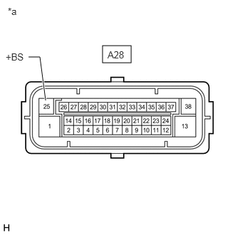
| *a | Front view of wire harness connector
(to Skid Control ECU (Brake Actuator Assembly)) |
Make sure that there is no looseness at the locking part and the connecting part of the connector.
- OK:
The connector is securely connected.
Disconnect the A28 skid control ECU (brake actuator assembly) connector.
Check both the connector case and the terminals for deformation and corrosion.
- OK:
No deformation or corrosion.
Measure the voltage according to the value(s) in the table below.
- Standard Voltage:
Tester Connection Condition Specified Condition A28-25 (+BS) - Body ground Always 11 to 14 V
- Result:
Proceed to OK NG
OK
NG
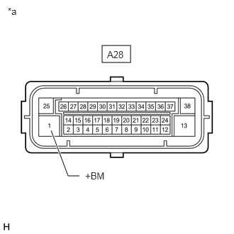
| *a | Front view of wire harness connector
(to Skid Control ECU (Brake Actuator Assembly)) |
Make sure that there is no looseness at the locking part and the connecting part of the connector.
- OK:
The connector is securely connected.
Disconnect the A28 skid control ECU (brake actuator assembly) connector.
Check both the connector case and the terminals for deformation and corrosion.
- OK:
No deformation or corrosion.
Measure the voltage according to the value(s) in the table below.
- Standard Voltage:
Tester Connection Condition Specified Condition A28-1 (+BM) - Body ground Always 11 to 14 V
- Result:
Proceed to OK NG
OK
NG