☰ Toyota HiAce☰ فهرستBrake › BRAKE CONTROL / DYNAMIC CONTROL SYSTEMS › ELECTRONICALLY CONTROLLED BRAKE SYSTEM(w/o VSC OFF Switch)
RM35X0E
_54
Brake
_078667
BRAKE CONTROL / DYNAMIC CONTROL SYSTEMS
_0383093
ELECTRONICALLY CONTROLLED BRAKE SYSTEM(w/o VSC OFF Switch)
U
BRAKE CONTROL / DYNAMIC CONTROL SYSTEMS ELECTRONICALLY CONTROLLED BRAKE SYSTEM(w/o VSC OFF Switch) TERMINALS OF ECU
TERMINALS OF ECU
0.125,0.146 0.427,0.354
0.302,0.208
10
false
*a
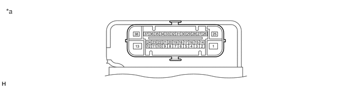
| *a | Component without harness connected
(Skid Control ECU (Brake Actuator Assembly)) |
- | - |
- HINT:
- ·
As a waterproof connector is used for the brake actuator assembly, voltage and waveform inspections cannot be performed with the connector connected.
- ·
Use the GTS to read data and perform Active Tests when inspecting the operation and communication status of the brake actuator assembly.
| Terminal No. (Symbol) | Terminal Description |
|---|---|
| 1 (+BM) | ABS motor relay power supply |
| 2 (SP1) | Speed signal output for speedometer |
| 3 | - |
| 4 (FR-) | Front wheel speed RH (-) signal input |
| 5 | - |
| 6 | - |
| 7 | - |
| 8 (FL-) | Front wheel speed LH (-) signal input |
| 9 (STP) | Stop light switch assembly signal input |
| 10 | - |
| 11 | - |
| 12 | - |
| 13 (GND2) | Pump motor ground |
| 14 (CANL) | CAN communication line L |
| 15 | - |
| 16 (FR+) | Front wheel speed RH (+) power supply output |
| 17 (RR+) | Rear wheel speed RH (+) power supply output |
| 18 (RL-) | Rear wheel speed LH (-) signal input |
| 19 (FL+) | Front wheel speed LH (+) power supply output |
| 20 | - |
| 21 | - |
| 22 | - |
| 23 | - |
| 24 | - |
| 25 (+BS) | ABS solenoid relay power supply |
| 26 (CANH) | CAN communication line H |
| 27 | - |
| 28 (IG1) | IG1 power source input |
| 29 (RR-) | Rear wheel speed RH (-) signal input |
| 30 | - |
| 31 (RL+) | Rear wheel speed LH (+) power supply output |
| 32 | - |
| 33 | - |
| 34 | - |
| 35 | - |
| 38 (GND1) | Skid control ECU (brake actuator assembly) ground |
TERMINAL INSPECTION
a.
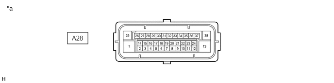
Disconnect the A28 skid control ECU (brake actuator assembly) connector and measure the voltage and resistance on the wire harness side.
1.448,0.698 1.885,0.948
0.438,0.25
0.146,0.094 0.458,0.25
0.313,0.156
10
false
*a
1.542,0.74 2,0.938
0.458,0.198
10
false
A28
| *a | Front view of wire harness connector
(to Skid Control ECU (Brake Actuator Assembly)) |
- | - |
b.
Measure the voltage or resistance according to the value(s) in the table below.
| Terminal No. (Symbol) | Wiring Color | Terminal Description | Condition | Specified Condition |
|---|---|---|---|---|
| A28-1 (+BM) - Body ground | R - Body ground | ABS motor relay power supply | Always | 11 to 14 V |
| A28-13 (GND2) - Body ground | W-B - Body ground | Pump motor ground | Always | Below 1 Ω |
| A28-25 (+BS) - Body ground | B - Body ground | ABS solenoid relay power supply | Always | 11 to 14 V |
| A28-28 (IG1) - Body ground | B - Body ground | IG1 power source input | Ignition switch ON | 11 to 14 V |
| A28-9 (STP) - Body ground | R - Body ground | Stop light switch assembly signal input | Stop light switch assembly on → off (Brake pedal depressed → released) | 11 to 14 V → 1.5 V or less |
| A28-38 (GND1) - Body ground | W-B - Body ground | Skid control ECU (brake actuator assembly) ground | Always | Below 1 Ω |