AC60E AUTOMATIC TRANSMISSION / TRANSAXLE SHIFT LEVER REASSEMBLY
CAUTION / NOTICE / HINT
- HINT:
- ·
Use the same procedure for RHD and LHD vehicles.
·The procedure listed below is for LHD vehicles.
PROCEDURE

 35970F
1.INSTALL POSITION INDICATOR HOUSING ASSEMBLY
35970F
1.INSTALL POSITION INDICATOR HOUSING ASSEMBLY
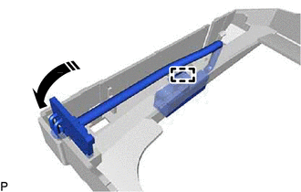

|
Install in this Direction |
Attach the clamp to install the indicator light wire sub-assembly to the lower position indicator housing.
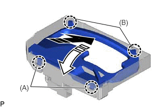
|
|
Install in this Direction |

|
Connect in this Direction |
Attach the 2 claws (B) and install the position indicator housing assembly to the lower position indicator housing assembly in the direction shown in the illustration.
Attach the 2 claws (A) and connect the position indicator plate control to the lower position indicator housing in the direction shown in the illustration.
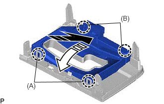
|
|
Install in this Direction |
|
|
Connect in this Direction |
Attach the 2 claws (B) and install the lower position indicator housing to the upper position indicator housing assembly in the direction shown in the illustration.
Attach the 2 claws (A) and connect the lower position indicator housing to the upper position indicator housing assembly in the direction shown in the illustration.
33554
2.INSTALL SHIFT LEVER CAP
Attach the 2 claws and install the shift lever cap to the position indicator housing assembly.
35976
3.INSTALL NO. 2 POSITION INDICATOR SLIDE COVER
Attach the claw and install the No. 2 position indicator slide cover to the position indicator slide cover.
35975
4.INSTALL POSITION INDICATOR SLIDE COVER
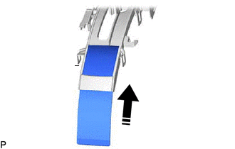
|
|
Install in this Direction |
Install the position indicator slide cover with No. 2 position indicator slide cover to the lower position indicator housing.
5.INSTALL SLIDE COVER SUB-ASSEMBLY
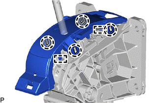
Attach the 4 claws and 2 guides to install the slide cover sub-assembly to the shift lock control unit assembly.