POWER ASSIST SYSTEMS POWER STEERING SYSTEM(w/ Variable Flow Control Solenoid Valve) Power Steering Warning Light Circuit
DESCRIPTION
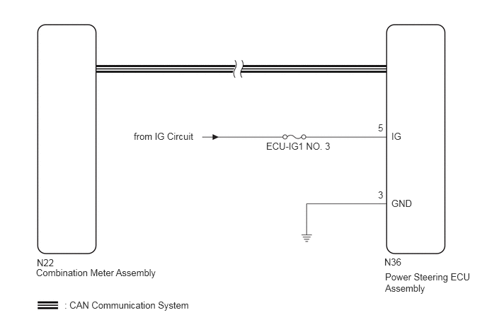
The power steering ECU assembly is connected to the combination meter via CAN communication. If the power steering ECU assembly detects a malfunction, the power steering warning light comes on. At this time, the vehicle enters fail-safe mode.
WIRING DIAGRAM
CAUTION / NOTICE / HINT
- NOTICE:
-
Inspect the fuses for circuits related to this system before performing the following inspection procedure.
PROCEDURE
- Result:
Result Proceed to CAN communication system DTCs are not output. A CAN communication system DTCs are output. B
A
B
Disconnect the power steering ECU assembly connector.
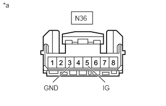
| *a | Front view of wire harness connector
(to Power Steering ECU Assembly) |
Measure the voltage according to the value(s) in the table below.
- Standard Voltage:
Tester Connection Switch Condition Specified Condition N36-5 (IG) - Body ground Ignition switch ON 11 to 14 V
Measure the resistance according to the value(s) in the table below.
- Standard Resistance:
Tester Connection Condition Specified Condition N36-3 (GND) - Body ground Always Below 1 Ω
- Result:
Proceed to OK NG
OK
NG
Connect the GTS to the DLC3.
Turn the ignition switch to ON and turn the GTS on.
Perform the Active Test of the combination meter using GTS.
- Body Electrical > Combination Meter > Active Test
-
Tester Display Measurement Item Control Range Diagnostic Note PPS Warning Power steering warning light OFF or ON Perform the test with the vehicle stopped and the engine idling.
- Body Electrical > Combination Meter > Active Test
-
Tester Display PPS Warning - 50004 409 129
Check that the power steering warning light operates in accordance with the Active Test.
- HINT:
-
Reconnect the connectors and restore the vehicle to its previous condition before checking the combination meter.
- OK:
The power steering warning light turns on and off in accordance with GTS operation.
- Result:
Proceed to OK NG
OK
NG