7GR-FKS STARTING STARTER REASSEMBLY
PROCEDURE

 28160
1.INSTALL STARTER ARMATURE ASSEMBLY
28160
1.INSTALL STARTER ARMATURE ASSEMBLY
Install the starter armature assembly to the starter yoke assembly.
28140
2.INSTALL STARTER BRUSH HOLDER ASSEMBLY
Install the starter brush holder assembly.
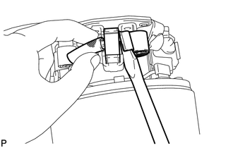
Connect the 4 brushes to the starter brush holder assembly.
Using a screwdriver, hold back the brush spring.
Connect the brush to the starter brush holder assembly.
- NOTICE:
-
Check that positive (+) lead wires are not grounded.
Place a new O-ring in position on the starter commutator end frame assembly.
Install the starter commutator end frame assembly with the 2 screws.
- Torque:
- 1.5 N*m (15 kgf*cm, 13 in.*lbf)
28150
3.INSTALL MAGNET STARTER SWITCH ASSEMBLY
Apply high-temperature grease to the idle gear, steel ball, return spring, clutch roller and retainer.
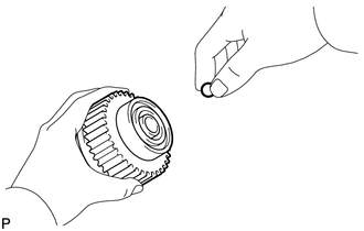
Insert the steel ball into the starter clutch hole.
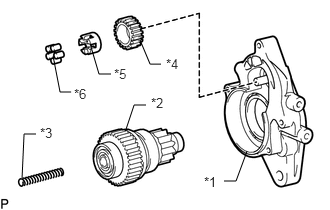
| *1 | Starter Drive Housing Assembly |
| *2 | Starter Clutch Sub-assembly |
| *3 | Return Spring |
| *4 | Idle Gear |
| *5 | Retainer |
| *6 | Clutch Roller |
Insert the return spring into the starter clutch hole.
Install the starter clutch sub-assembly, idle gear, retainer and clutch roller to the starter drive housing assembly.
Install the starter drive housing assembly to the magnet starter switch assembly with the 2 bolts.
- Torque:
- 5.9 N*m (60 kgf*cm, 52 in.*lbf)
28120
4.INSTALL STARTER YOKE ASSEMBLY
Install a new O-ring to the groove of the starter yoke assembly.
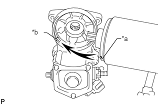
| *a | Claw |
| *b | Groove |
Align the claw of the starter yoke assembly with the groove of the magnet starter switch assembly.
Install the starter yoke assembly to the magnet starter switch assembly with the 2 bolts.
- Torque:
- 5.9 N*m (60 kgf*cm, 52 in.*lbf)
Connect the lead wire to terminal C with the nut.
- Torque:
- 5.9 N*m (60 kgf*cm, 52 in.*lbf)