BRAKE SYSTEM (OTHER) VACUUM PUMP(for 7GR-FKS) INSTALLATION
PROCEDURE

 29300
1.INSTALL VACUUM PUMP ASSEMBLY
29300
1.INSTALL VACUUM PUMP ASSEMBLY
When using a new vacuum pump assembly:

| *1 | No. 2 O-ring |
| *2 | No. 3 O-ring |

|
Engine Oil |
Apply engine oil to the No. 2 O-ring and No. 3 O-ring which are installed to a new vacuum pump assembly.
When reusing the vacuum pump assembly:
| *1 | No. 2 O-ring |
| *2 | No. 3 O-ring |
|
|
Engine Oil |
Apply engine oil to a new No. 2 O-ring and No. 3 O-ring and install them to the vacuum pump assembly.
Apply engine oil to the inner surface of the installation hole.
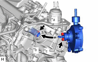
| *a | Coupling Teeth |
| *b | Groove |
| *c | Oil Pipe |
Temporarily install the vacuum pump assembly so that the oil pipe engages with the hole of the camshaft and the coupling teeth engages with the groove of the camshaft.
- NOTICE:
- ·
Ensure that the vacuum pump assembly is installed securely.
·Be careful not to pinch the O-ring.

Install the vacuum pump assembly with the 3 bolts.
- Torque:
- 21 N*m (214 kgf*cm, 15 ft.*lbf)
- NOTICE:
- ·
After installation, check that there are no gaps between the matching surfaces and that the vacuum pump assembly is not installed at an angle.
·Tighten the 3 bolts in the order shown in the illustration.
87249B
2.CONNECT OUTLET HEATER WATER PIPE B
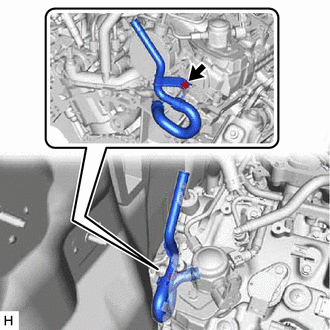
Install the outlet heater water pipe B to the engine assembly with the bolt.
- Torque:
- 9.8 N*m (100 kgf*cm, 87 in.*lbf)
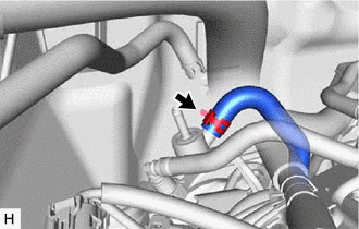
Connect the outlet heater water hose B to the outlet heater water pipe B and slide the clip to secure it.
3.CONNECT VACUUM HOSE ASSEMBLY
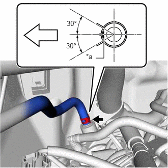
| *a | Paint Mark |

|
Front of the vehicle |
Slide the clip and disconnect the vacuum hose assembly from the vacuum pump assembly.
- NOTICE:
- ·
When connecting the vacuum hose assembly, face the front of the vehicle.
·Install the clip within the range shown in the illustration.
4.INSPECT VACUUM PUMP OPERATION