7GR-FKS ENGINE MECHANICAL CYLINDER HEAD REPLACEMENT
PROCEDURE

 11122C
1.REPLACE INTAKE VALVE GUIDE BUSH
11122C
1.REPLACE INTAKE VALVE GUIDE BUSH
Heat the cylinder head to 80 to 100°C (176 to 212°F).
Place the cylinder head on wooden blocks.
- CAUTION:
-
Be sure to wear protective gloves.
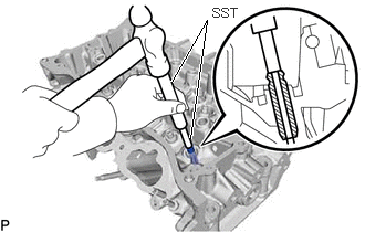
Using SST and a hammer, tap out the intake valve guide bushes.
- SST
- 09201-10000 (09201-01050)
09950-70010 (09951-07100)
Using a caliper gauge, measure the intake valve guide bush bore diameter of the cylinder head.
- Standard cylinder bore diameter:
10.285 to 10.306 mm (0.4049 to 0.4057 in.)
- Select a New Guide Bush (STD or O/S 0.05):
Bush Size Specified Condition STD 10.333 to 10.344 mm (0.40681 to 0.40724 in.) O/S 0.05 10.383 to 10.394 mm (0.40878 to 0.40921 in.)
If the bush bore diameter of the cylinder head is more than 10.306 mm (0.4057 in.), machine the bush bore to the dimension of 10.335 to 10.356 mm (0.4069 to 0.4077 in.) to install an O/S 0.05 valve guide bush.
If the bush bore diameter of the cylinder head is more than 10.356 mm (0.4077 in.), replace the cylinder head.
Heat the cylinder head to 80 to 100°C (176 to 212°F).
Place the cylinder head on wooden blocks.
- CAUTION:
-
Be sure to wear protective gloves.
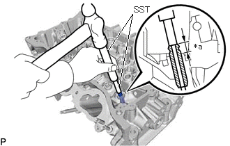
| *a | Protrusion Height |
Using SST, tap in new intake valve guide bushes to the specified protrusion height.
- SST
- 09201-10000 (09201-01050)
09950-70010 (09951-07100)
- Standard protrusion height:
9.10 to 9.90 mm (0.358 to 0.390 in.)
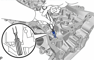
Using a sharp 5.5 mm reamer, ream the valve guide bushings to obtain the specified clearance.
- Standard oil clearance:
0.025 to 0.060 mm (0.000984 to 0.00236 in.)
11126C
2.REPLACE EXHAUST VALVE GUIDE BUSH
Heat the cylinder head to 80 to 100°C (176 to 212°F).
Place the cylinder head on wooden blocks.
- CAUTION:
-
Be sure to wear protective gloves.
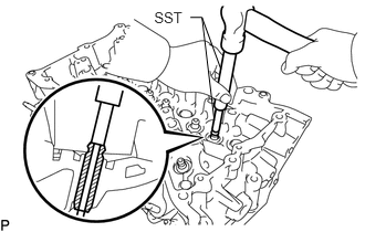
Using SST and a hammer, tap out the exhaust valve guide bushes.
- SST
- 09201-10000 (09201-01050)
09950-70010 (09951-07100)
Using a caliper gauge, measure the exhaust valve guide bush bore diameter of the cylinder head.
- Standard cylinder bore diameter:
10.285 to 10.306 mm (0.4049 to 0.4057 in.)
- Select a New Guide Bush (STD or O/S 0.05):
Bush Size Specified Condition STD 10.333 to 10.344 mm (0.40681 to 0.40724 in.) O/S 0.05 10.383 to 10.394 mm (0.40878 to 0.40921 in.)
If the bush bore diameter of the cylinder head is more than 10.306 mm (0.4057 in.), machine the bush bore to the dimension of 10.335 to 10.356 mm (0.4069 to 0.4077 in.) to install an O/S 0.05 valve guide bush.
If the bush bore diameter of the cylinder head is more than 10.356 mm (0.4077 in.), replace the cylinder head.
Heat the cylinder head to 80 to 100°C (176 to 212°F).
Place the cylinder head on wooden blocks.
- CAUTION:
-
Be sure to wear protective gloves.
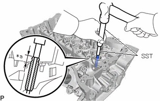
| *a | Protrusion Height |
Using SST, tap in new exhaust valve guide bushes to the specified protrusion height.
- SST
- 09201-10000 (09201-01050)
09950-70010 (09951-07100)
- Standard protrusion height:
9.10 to 9.90 mm (0.358 to 0.390 in.)
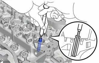
Using a sharp 5.5 mm reamer, ream the valve guide bushings to obtain the specified clearance.
- Standard oil clearance:
0.030 to 0.065 mm (0.00118 to 0.00256 in.)
3.REPLACE RING PIN
- NOTICE:
-
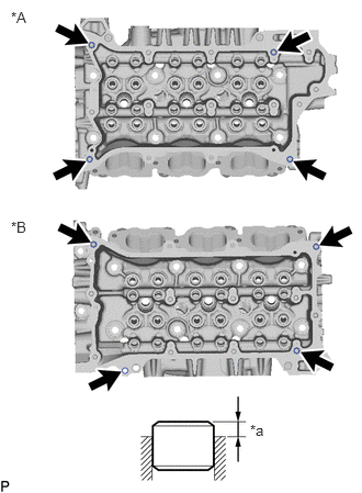 0.104,0.083 0.417,0.24 0.313,0.156 10 false *A 0.104,2.073 0.417,2.229 0.313,0.156 10 false *B 2.375,4 2.688,4.156 0.313,0.156 10 false *a
*A for Bank 1 *B for Bank 2 *a Protrusion Height
-
It is not necessary to remove the ring pin unless it is being replaced.
Using a plastic-faced hammer, tap in new ring pins to the specified protrusion height.
- Standard protrusion height:
2.5 to 3.5 mm (0.0984 to 0.138 in.)
11114A
4.REPLACE STRAIGHT PIN
- NOTICE:
-
It is not necessary to remove the straight pin unless it is being replaced.
Using a plastic-faced hammer, tap in new straight pins as shown in the illustration.

| *A | for Bank 1 | *B | for Bank 2 |
| *a | Protrusion Height | *b | 34 mm (1.34 in.) |
- Standard protrusion height:
17.5 to 19.5 mm (0.689 to 0.768 in.)