7GR-FKS ENGINE MECHANICAL CYLINDER HEAD INSPECTION
PROCEDURE

 11101
1.INSPECT CYLINDER HEAD SUB-ASSEMBLY
11101
1.INSPECT CYLINDER HEAD SUB-ASSEMBLY
Using a precision straightedge and feeler gauge, measure the warpage of the contact surfaces where the cylinder head sub-assembly contacts the cylinder block sub-assembly and manifolds.
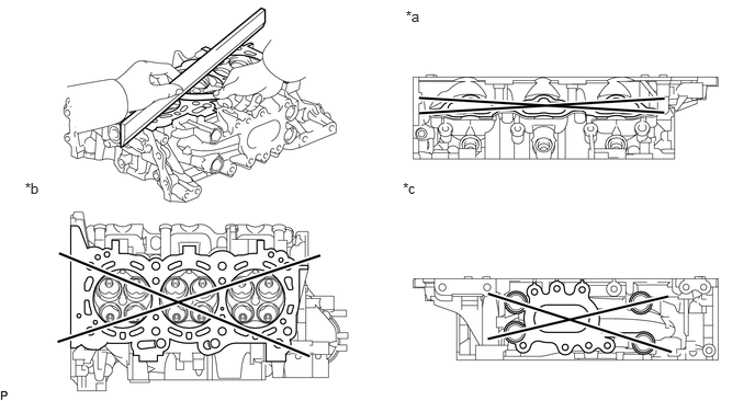
| *a | Intake Side | *b | Cylinder Block Side |
| *c | Exhaust Side | - | - |
- Standard Warpage:
Item Specified Condition Cylinder Block Side 0 to 0.05 mm (0 to 0.00197 in.) Exhaust Side 0 to 0.08 mm (0 to 0.00315 in.) Intake Side 0 to 0.08 mm (0 to 0.00315 in.)
- Maximum warpage:
0.10 mm (0.00394 in.)
If the warpage is more than the maximum, replace the cylinder head sub-assembly.
2.INSPECT CYLINDER HEAD FOR CRACKS
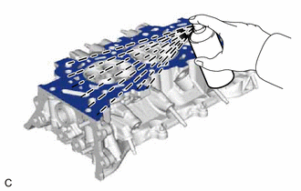
Using a dye penetrant, check the intake ports, exhaust ports and cylinder surface for cracks.
- HINT:
-
If cracked, replace the cylinder head sub-assembly.
13711
3.INSPECT INTAKE VALVE
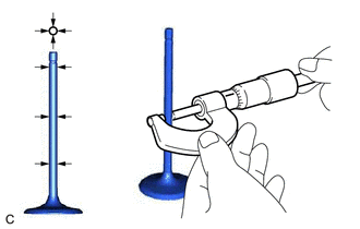
Using a micrometer, measure the diameter of the valve stem.
- Standard Valve Stem Diameter:
5.470 to 5.485 mm (0.215 to 0.216 in.)
- HINT:
-
If the valve stem diameter is not as specified, check the intake valve guide bush oil clearance.
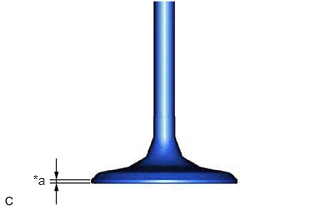
| *a | Margin Thickness |
Using a vernier caliper, measure the valve head margin thickness.
- Standard Margin Thickness:
1.0 mm (0.0394 in.)
- Minimum Margin Thickness:
0.5 mm (0.0197 in.)
- HINT:
-
If the margin thickness is less than the minimum, replace the intake valve.
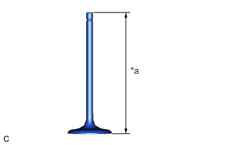
| *a | Overall Length |
Using a vernier caliper, measure the overall length of the intake valve.
- Standard Overall Length:
105.85 mm (4.17 in.)
- Minimum Overall Length:
105.35 mm (4.15 in.)
- HINT:
-
If the overall length is less than the minimum, replace the intake valve.
13715
4.INSPECT EXHAUST VALVE
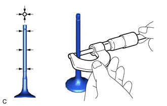
Using a micrometer, measure the diameter of the valve stem.
- Standard Valve Stem Diameter:
5.465 to 5.480 mm (0.215 to 0.216 in.)
- HINT:
-
If the valve stem diameter is not as specified, check the exhaust valve guide bush oil clearance.
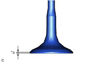
| *a | Margin Thickness |
Using a vernier caliper, measure the valve head margin thickness.
- Standard Margin Thickness:
1.0 mm (0.0394 in.)
- Minimum Margin Thickness:
0.5 mm (0.0197 in.)
- HINT:
-
If the margin thickness is less than the minimum, replace the exhaust valve.
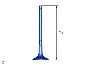
| *a | Overall Length |
Using a vernier caliper, measure the overall length of the exhaust valve.
- Standard Overall Length:
110.40 mm (4.35 in.)
- Minimum Overall Length:
109.90 mm (4.33 in.)
- HINT:
-
If the overall length is less than the minimum, replace the exhaust valve.
11131
5.INSPECT INTAKE VALVE SEAT
Apply a light coat of Prussian blue to the valve face.
Lightly press the valve face against the intake valve seat.
- NOTICE:
-
Do not rotate the intake valve while pressing it.
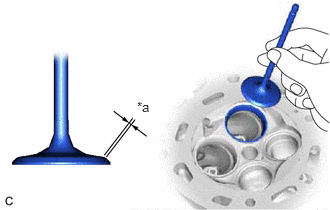
| *a | Width |
Check the valve face and intake valve seat by using the following procedure:
If Prussian blue appears 360° around the entire intake valve face, the valve face is concentric.
- HINT:
-
If the valve face is not concentric, replace the intake valve.
If Prussian blue appears 360° around the entire intake valve seat, the intake valve seat and valve face are concentric.
- HINT:
-
If the valve face is not concentric, resurface the intake valve seat.
Measure the width of the contact area of the intake valve seat and valve face.
- Standard Width:
1.1 to 1.5 mm (0.0433 to 0.0591 in.)
11135B
6.INSPECT EXHAUST VALVE SEAT
Apply a light coat of Prussian blue to the valve face.
Lightly press the valve face against the exhaust valve seat.
- NOTICE:
-
Do not rotate the exhaust valve while pressing it.
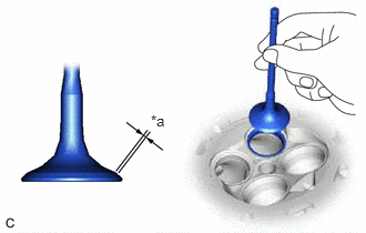
| *a | Width |
Check the valve face and exhaust valve seat by using the following procedure:
If Prussian blue appears 360° around the entire exhaust valve face, the valve face is concentric.
- HINT:
-
If the valve face is not concentric, replace the exhaust valve.
If Prussian blue appears 360° around the entire exhaust valve seat, the exhaust valve seat and valve face are concentric.
- HINT:
-
If the valve face is not concentric, resurface the exhaust valve seat.
Measure the width of the contact area of the exhaust valve seat and valve face.
- Standard Width:
1.1 to 1.5 mm (0.0433 to 0.0591 in.)
13711B
7.INSPECT COMPRESSION SPRING
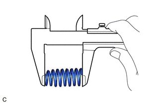
Using a vernier caliper, measure the free length of the inner compression spring.
- Standard Free Length:
54.53 mm (2.15 in.)
- Minimum Free Length:
52.43 mm (2.06 in.)
- HINT:
-
If the free length is less than the minimum, replace the inner compression spring.
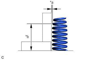
| *a | Deviation |
| *b | 40 mm (1.57 in.) |
Using a steel square, measure the deviation of the inner compression spring.
- Maximum Deviation (Reference):
1.4 mm (0.0551 in.)
- HINT:
-
If the deviation is more than the maximum, replace the inner compression spring.
8.INSPECT VALVE GUIDE BUSH OIL CLEARANCE
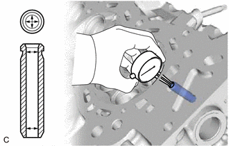
Using a caliper gauge, measure the inside diameter of the valve guide bush.
- Standard Valve Guide Bush Inside Diameter:
5.510 to 5.530 mm (0.217 to 0.218 in.)
Subtract the valve stem diameter measurement from the valve guide bush inside diameter measurement.
- Standard Oil Clearance:
Item Specified Condition Intake 0.025 to 0.060 mm (0.000984 to 0.00236 in.) Exhaust 0.030 to 0.065 mm (0.00118 to 0.00256 in.)
- Maximum Oil Clearance:
Item Specified Condition Intake 0.08 mm (0.00315 in.) Exhaust 0.085 mm (0.00335 in.)
- HINT:
-
If the oil clearance is more than the maximum, replace the valve and valve guide bush.
9.INSPECT CAMSHAFT THRUST CLEARANCE
Inspect the camshaft thrust clearance (for Bank 1).
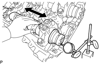
Using a dial indicator, measure the thrust clearance while moving the camshaft back and forth.
- Standard thrust clearance:
0.08 to 0.13 mm (0.00315 to 0.00512 in.)
- Maximum thrust clearance:
0.15 mm (0.00591 in.)
- HINT:
- ·
If the thrust clearance is more than the maximum, replace the camshaft housing sub-assembly.
·If the thrust surface is damaged, replace the camshaft or No. 2 camshaft.
Inspect the camshaft thrust clearance (for Bank 2).
Install the No. 3 camshaft sub-assembly.
Install the No. 4 camshaft sub-assembly.
Using a dial indicator, measure the thrust clearance while moving the camshaft back and forth.
- Standard thrust clearance:
0.08 to 0.13 mm (0.00315 to 0.00512 in.)
- Maximum thrust clearance:
0.15 mm (0.00591 in.)
- HINT:
- ·
If the thrust clearance is more than the maximum, replace the camshaft housing sub-assembly LH.
·If the thrust surface is damaged, replace the No. 3 camshaft sub-assembly or No. 4 camshaft sub-assembly.