7GR-FKS ENGINE MECHANICAL ENGINE UNIT INSTALLATION
PROCEDURE

 89422P
1.INSTALL ENGINE COOLANT TEMPERATURE SENSOR
89422P
1.INSTALL ENGINE COOLANT TEMPERATURE SENSOR
83530
2.INSTALL ENGINE OIL PRESSURE SWITCH ASSEMBLY
19500
3.INSTALL IGNITION COIL ASSEMBLY
23255A
4.INSTALL FUEL INJECTOR SEAL
23250E
5.INSTALL DIRECT FUEL INJECTOR ASSEMBLY
23814E
6.INSTALL FUEL DELIVERY PIPE RH
23860
7.INSTALL FUEL DELIVERY WITH SENSOR PIPE ASSEMBLY LH
23802B
8.INSTALL NO. 2 FUEL PIPE SUB-ASSEMBLY
23100X
9.TEMPORARILY INSTALL FUEL PUMP ASSEMBLY
23801P
10.TEMPORARILY INSTALL NO. 1 FUEL PIPE SUB-ASSEMBLY
23100X
11.INSTALL FUEL PUMP ASSEMBLY
23801P
12.INSTALL NO. 1 FUEL PIPE SUB-ASSEMBLY
17111
13.INSTALL INTAKE MANIFOLD
82121
14.INSTALL ENGINE WIRE
16268
15.INSTALL NO. 1 WATER BY-PASS PIPE
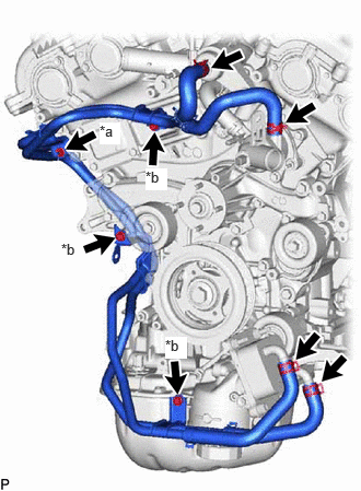
| *a | Nut |
| *b | Bolt |
Install the No. 1 water by-pass pipe with the 3 bolts and nut as shown in the illustration.
- Torque:
- 10 N*m (102 kgf*cm, 7 ft.*lbf)
Connect the 4 hoses and slide the 4 hose clamps to secure the 4 hoses.
16267
16.INSTALL NO. 3 WATER BY-PASS HOSE
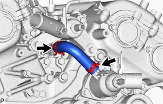
Install the No. 3 water by-pass hose and slide the 2 hose clamps to secure the hose.
16264
17.INSTALL NO. 2 WATER BY-PASS HOSE
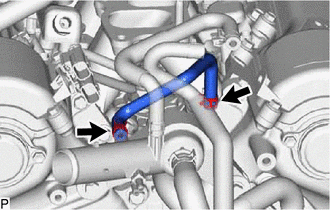
Install the No. 2 water by-pass hose and slide the 2 hose clamps to secure the hose.
16261
18.INSTALL NO. 1 WATER BY-PASS HOSE
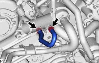
Install the No. 1 water by-pass hose and slide the 2 hose clamps to secure the hose.
16282
19.INSTALL NO. 5 WATER BY-PASS HOSE
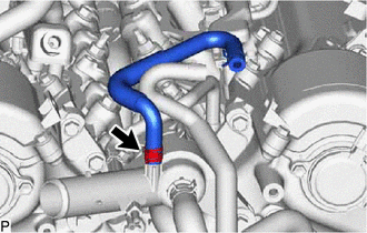
Install the No. 5 water by-pass hose and slide the hose clamp to secure the hose.
20.INSTALL NO. 4 WATER BY-PASS HOSE
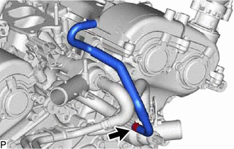
Install the No. 4 water by-pass hose and slide the hose clamp to secure the hose.
16620
21.INSTALL V-RIBBED BELT TENSIONER ASSEMBLY
Install the V-ribbed belt tensioner assembly with the 2 bolts.
- Torque:
- 43 N*m (438 kgf*cm, 32 ft.*lbf)
16604
22.INSTALL NO. 2 IDLER PULLEY SUB-ASSEMBLY
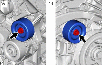
| *A | LH Side |
| *B | RH Side |
Install the 2 No. 2 idler pulley sub-assemblies with the 2 bolts.
- Torque:
- 43 N*m (438 kgf*cm, 32 ft.*lbf)
16603
23.INSTALL NO. 1 IDLER PULLEY SUB-ASSEMBLY
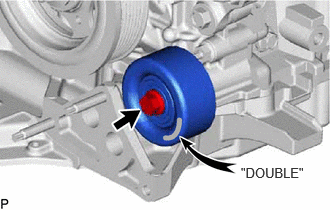
Install the No. 1 idler pulley sub-assembly with the bolt.
- Torque:
- 54 N*m (551 kgf*cm, 40 ft.*lbf)
- HINT:
-
"DOUBLE" is marked on the idler pulley to distinguish it from the No. 2 idler pulley.
12315
24.INSTALL FRONT NO. 1 ENGINE MOUNTING BRACKET LH
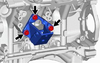
Install the front No. 1 engine mounting bracket LH with the 3 bolts.
- Torque:
- 43 N*m (438 kgf*cm, 32 ft.*lbf)
12311
25.INSTALL FRONT NO. 1 ENGINE MOUNTING BRACKET RH

Install the front No. 1 engine mounting bracket RH with the 4 bolts.
- Torque:
- 43 N*m (438 kgf*cm, 32 ft.*lbf)
88431
26.INSTALL NO. 1 COMPRESSOR MOUNTING BRACKET
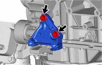
Install the No. 1 compressor mounting bracket with the 2 bolts.
- Torque:
- 45 N*m (459 kgf*cm, 33 ft.*lbf)
29300
27.INSTALL VACUUM PUMP ASSEMBLY
28.INSTALL HEATER WATER HOSE ASSEMBLY
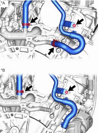
| *A | w/o ATF Warmer |
| *B | w/ ATF Warmer |
w/o ATF Warmer:
Connect the heater water hose assembly to the rear water by-pass joint, and slide the clip to secure the hose.
Connect the heater water hose assembly to the No. 1 water outlet pipe, and slide the clip to secure the hose.
Install the heater water hose assembly with the bolt.
- Torque:
- 9.8 N*m (100 kgf*cm, 87 in.*lbf)
w/ ATF Warmer:
Connect the heater water hose assembly to the rear water by-pass joint, and slide the clip to secure the hose.
Install the heater water hose assembly with the bolt.
- Torque:
- 9.8 N*m (100 kgf*cm, 87 in.*lbf)
23901
29.INSTALL FUEL TUBE SUB-ASSEMBLY AND NO. 2 FUEL TUBE SUB-ASSEMBLY
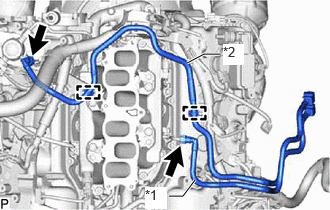
| *1 | Fuel Tube Sub-assembly |
| *2 | No. 2 Fuel Tube Sub-assembly |
Connect the No. 2 fuel tube sub-assembly.
Attach the 2 clamps and connect the No. 2 fuel tube sub-assembly.
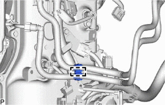
Attach the 2 clamps and install the fuel tube clamp.
12262
30.INSTALL NO. 2 PCV HOSE
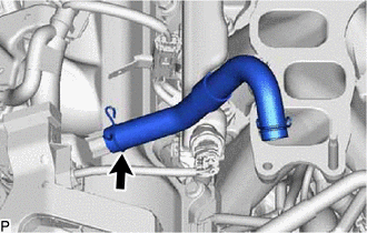
Install the No. 2 PCV hose to the cylinder head cover sub-assembly, and slide the clip to secure it.
12261
31.INSTALL PCV HOSE
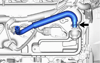
Install the PCV hose to the PCV valve, and slide the clip to secure it.
17360G
32.INSTALL AIR TUBE ASSEMBLY (w/ Secondary Air Injection System)
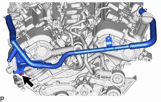
Install the air tube assembly with the bolt.
- Torque:
- 10 N*m (102 kgf*cm, 7 ft.*lbf)
33.INSTALL AIR SWITCHING VALVE ASSEMBLY (w/ Secondary Air Injection System)