SEAT REAR SEAT ASSEMBLY(for Commuter, Single-Passenger Seat with 3-Point Type Seat Belt) REASSEMBLY
CAUTION / NOTICE / HINT
- CAUTION:
- ·
Wear protective gloves. Sharp areas on the parts may injure your hands.
·There is risk of injury.
- HINT:
- ·
Use the same procedure for RHD and LHD vehicles.
·The procedure listed below is for LHD vehicles.
·The procedure listed below is a representative example.
·Use the same procedure for all rows, unless otherwise specified.
PROCEDURE

 79280B
1.INSTALL NO. 1 SEATBACK SPRING ASSEMBLY RH
79280B
1.INSTALL NO. 1 SEATBACK SPRING ASSEMBLY RH
w/ Seatback Board:
Attach the guide.
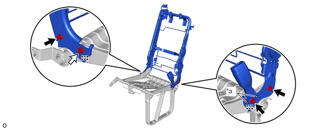
| *a | Protruding Part | - | - |

|
Bolt A | 
|
Bolt B |
Temporarily install the No. 1 seatback spring assembly RH and rear 1 person seat belt assembly with the 4 bolts.
- NOTICE:
-
Do not allow the rear 1 person seat belt assembly to overlap the protruding part.
Tighten the 3 bolts A.
- Torque:
- 42 N*m (428 kgf*cm, 31 ft.*lbf)
Remove the bolt B.
w/o Seatback Board:
Attach the guide.
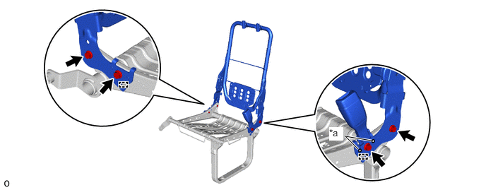
| *a | Protruding Part | - | - |
Temporarily install the No. 1 seatback spring assembly RH and rear 1 person seat belt assembly with the 4 bolts.
- NOTICE:
-
Do not allow the rear 1 person seat belt assembly to overlap the protruding part.
Tighten the 4 bolt.
- Torque:
- 42 N*m (428 kgf*cm, 31 ft.*lbf)
72345N
2.INSTALL NO. 1 SEAT STAND FRAME CAP RH
for Type A:
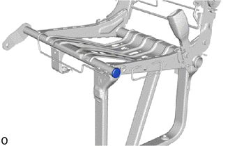
Install the No. 1 seat stand frame cap RH.
for Type B:
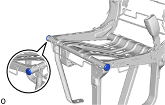
Install the 2 No. 1 seat stant frame caps RH.
71T76B
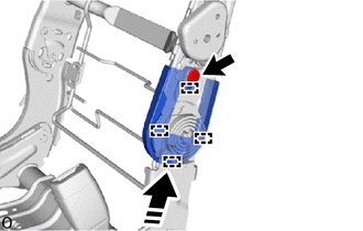
3.INSTALL RECLINING ADJUSTER INSIDE COVER LH (w/ Seatback Board)

|
Install in this Direction |
Attach the guide and install the reclining adjuster inside cover LH as shown in the illustration.
Install the clip.
72552K
4.INSTALL RH SEAT RECLINING HINGE COVER LH
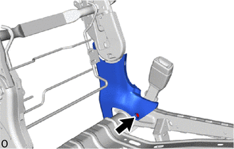
w/ Seatback Board:
Install the RH seat reclining hinge cover LH with the screw.
w/o Seatback Board:
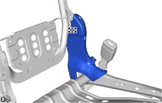
Attach the guide and install the RH seat reclining hinge cover LH.
72551M
5.INSTALL RH SEAT RECLINING HINGE COVER RH
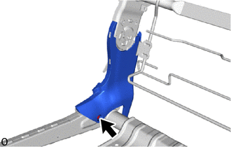
w/ Seatback Board:
Install the RH seat reclining hinge cover RH with the screw.
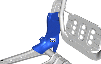
w/o Seatback Board:
Attach the guide and install the RH seat reclining hinge cover RH.
6.INSTALL SEAT COVER WIRE
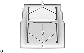
Install the seat cover wire.
- HINT:
- ·
Wire 1000 mm (3.28 ft.) or longer and shaped wire are available as supplied parts.
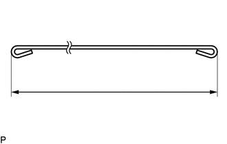
·For wire 1000 mm (3.28 ft.) or less in length, cut or shape 1000 mm (3.28 ft.) wire into the dimensions shown in the illustration.
·Make sure to read the precautions before preparing the wire.
- Dimensions:
A 120 mm (4.72 in.) B 210 mm (8.27 in.)
- HINT:
-
-
The dimensions shown in the illustration are the length.
79011E
7.INSTALL NO. 1 SEAT CUSHION COVER SUB-ASSEMBLY
- HINT:
-
When installing a No. 1 seat cushion cover sub-assembly, refer to the Precaution section in order to prevent wrinkles from forming.
Set the No. 1 seat cushion cover sub-assembly on the No. 1 seat cushion pad.
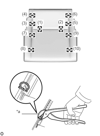
| *a | Hog Ring Pliers |
Using hog ring pliers, install the No. 1 seat cushion cover sub-assembly to the No. 1 seat cushion pad with 10 new hog rings in the order indicated in the illustration.
- NOTICE:
- ·
Be careful not to damage the No. 1 seat cushion cover sub-assembly.
·Be sure to securely install the hog rings as shown in the illustration while preventing wrinkles from forming on the No. 1 seat cushion cover sub-assembly.
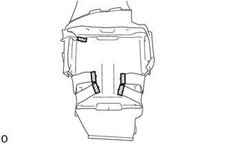

|
Fastening Tape |
Attach the fastening tape.
8.INSTALL SEAT CUSHION COVER WITH PAD
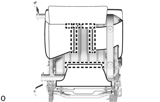
Attach the hook and install the seat cushion cover with pad as shown in the illustration.
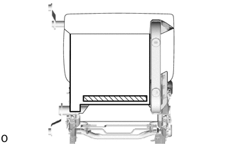
|
|
Fastening Tape |
Attach the fastening tape.
73343
9.INSTALL REAR SEAT SHOULDER BELT GUIDE RH (w/ Seatback Board)
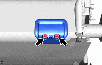
Attach the guide and install the rear seat shoulder belt guide RH.
Install the 2 screws.
73C73G
10.INSTALL REAR NO. 4 SEAT SHOULDER BELT COVER RH (w/ Seatback Board)
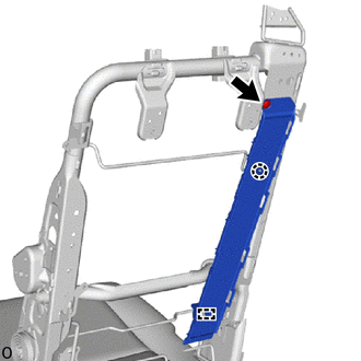
Attach the guide and claw and install the rear No. 4 seat shoulder belt cover RH.
Install the clip.
73360
11.INSTALL REAR SEAT OUTER 3 POINT TYPE BELT ASSEMBLY RH (w/ Seatback Board)
73C73H
12.INSTALL REAR SEAT SHOULDER BELT HOLE COVER RH (w/ Seatback Board)
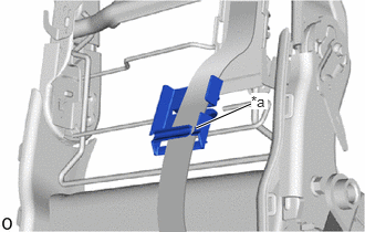
| *a | Slit |
Pass the rear seat outer 3 point type belt assembly RH through the slit of the rear seat shoulder belt hole cover RH.
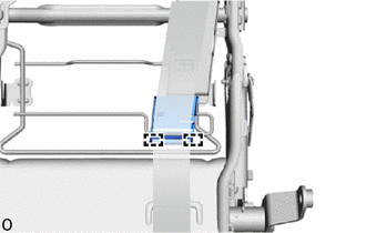
Attach the guide.
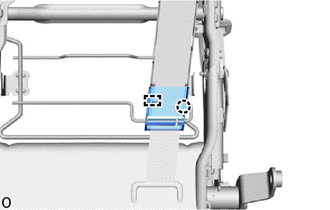
Attach the guide and claw and install the rear seat shoulder belt hole cover RH.
73C73F
13.INSTALL REAR NO. 3 SEAT SHOULDER BELT COVER RH (w/ Seatback Board)
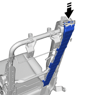
|
|
Install in this Direction |
Attach the guide as shown in the illustration.
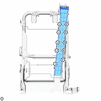
Attach the claw and install the rear No. 3 seat shoulder belt cover RH.
79175F
14.INSTALL NO. 1 SEATBACK PAD RH
w/ Seatback Board:
Pass the rear seat outer 3 point type belt assembly RH through the hole of the No. 1 seatback pad RH.
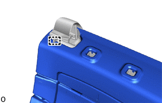
Attach the guide and install the No. 1 seatback pad RH.
w/o Seatback Board:
Install the No. 1 seatback pad RH.
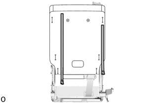
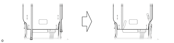
15.INSTALL SEAT COVER WIRE
Install the seat cover wire.
- HINT:
- ·
Wire 1000 mm (3.28 ft.) or longer and shaped wire are available as supplied parts.
·For wire 1000 mm (3.28 ft.) or less in length, cut or shape 1000 mm (3.28 ft.) wire into the dimensions shown in the illustration.
·Make sure to read the precautions before preparing the wire.
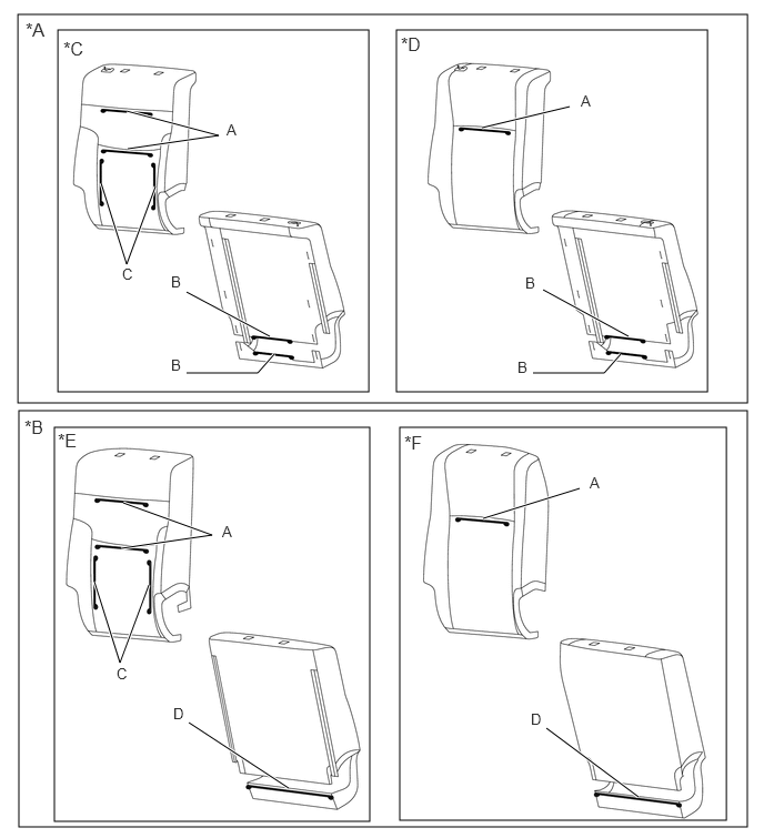
| *A | w/ Seatback Board | *B | w/o Seatback Board |
| *C | for Type A | *D | for Type B |
| *E | w/ Seatback Fastener | *F | w/o Seatback Fastener |
- Dimensions:
A 210 mm (8.27 in.) B 160 mm (6.29 in.) C 260 mm (10.2 in.) D 320 mm (1.05 ft.)
- HINT:
-
-
The dimensions shown in the illustration are the length.
79013D
16.INSTALL NO. 1 SEATBACK COVER SUB-ASSEMBLY RH (w/ Seatback Board)
- HINT:
-
When installing a No. 1 seatback cover sub-assembly RH, refer to the Precaution section in order to prevent wrinkles from forming.
Pass the rear seat outer 3 point type belt assembly RH through the hole of the No. 1 seatback cover sub-assembly RH.
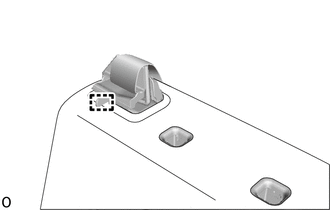
Attach the guide.
for Type A:
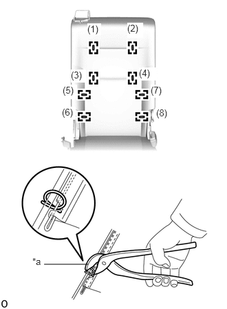
| *a | Hog Ring Pliers |
Using hog ring pliers, install the 8 new hog rings in the order indicated in the illustration.
- NOTICE:
- ·
Be careful not to damage the No. 1 seatback cover sub-assembly RH.
·Be sure to securely install the hog rings as shown in the illustration while preventing wrinkles from forming on the No. 1 seatback cover sub-assembly RH.
for Type B:
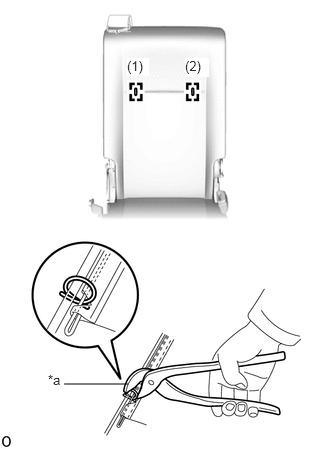
| *a | Hog Ring Pliers |
Using hog ring pliers, install the 2 new hog rings in the order indicated in the illustration.
- NOTICE:
- ·
Be careful not to damage the No. 1 seatback cover sub-assembly RH.
·Be sure to securely install the hog rings as shown in the illustration while preventing wrinkles from forming on the No. 1 seatback cover sub-assembly RH.
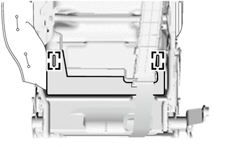
Insert the No. 1 seatback cover sub-assembly RH under the rear seat shoulder belt hole cover RH.
Attach the hook.
Attach the hook.
Close the 2 fasteners.
Insert the 2 fasteners.
| *a | Hog Ring Pliers |
Using hog ring pliers, install the No. 1 seatback cover sub-assembly RH with the 2 new hog rings in the order indicated in the illustration.
- NOTICE:
- ·
Be careful not to damage the No. 1 seatback cover sub-assembly RH.
·Be sure to securely install the hog rings as shown in the illustration while preventing wrinkles from forming on the No. 1 seatback cover sub-assembly RH.
|
|
Install in this Direction |
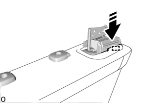
Attach the guide as shown in the illustration.
|
|
Install in this Direction |
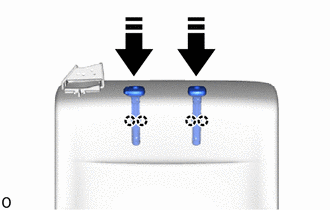
Attach the claw and install the 2 rear seat headrest supports as shown in the illustration.
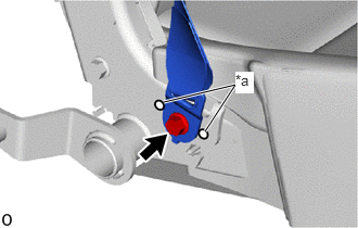
| *a | Protruding Part |
Install the anchor of the rear seat outer 3 point type belt assembly RH with the bolt.
- Torque:
- 42 N*m (428 kgf*cm, 31 ft.*lbf)
- NOTICE:
-
Do not allow the anchor of the rear seat outer 3 point type belt assembly RH to overlap the protruding part.
Check that the ELR locks.
With the rear seat outer 3 point type belt assembly RH installed to the vehicle, check that the belt locks when it is pulled out quickly.
79013D
17.INSTALL NO. 1 SEATBACK COVER SUB-ASSEMBLY RH (w/o Seatback Board)
- HINT:
-
When installing a No. 1 seatback cover sub-assembly RH, refer to the Precaution section in order to prevent wrinkles from forming.
for Type A:
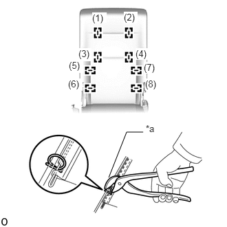
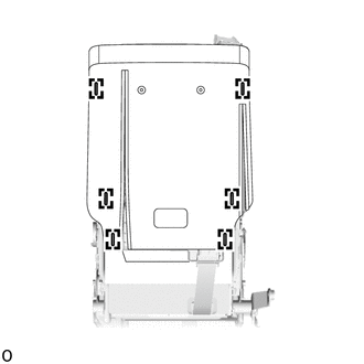
| *a | Hog Ring Pliers |
Using hog ring pliers, install the 8 new hog rings in the order indicated in the illustration.
- NOTICE:
- ·
Be careful not to damage the No. 1 seatback cover sub-assembly RH.
·Be sure to securely install the hog rings as shown in the illustration while preventing wrinkles from forming on the No. 1 seatback cover sub-assembly RH.
for Type B:
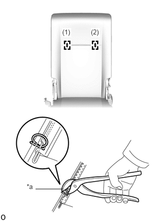
| *a | Hog Ring Pliers |
Using hog ring pliers, install the 2 new hog rings in the order indicated in the illustration.
- NOTICE:
- ·
Be careful not to damage the No. 1 seatback cover sub-assembly RH.
·Be sure to securely install the hog rings as shown in the illustration while preventing wrinkles from forming on the No. 1 seatback cover sub-assembly RH.
w/ Seatback fastener:
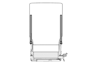
Close the 2 fasteners.
Insert the 2 fasteners.
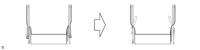
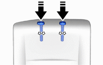
|
|
Install in this Direction |
Attach the claw and install the 2 rear seat seat headrest supports as shown in the illustration.
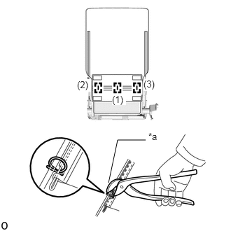
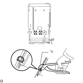
| *a | Hog Ring Pliers |
Using hog ring pliers, install the No. 1 seatback cover sub-assembly RH with the 3 new hog rings in the order indicated in the illustration.
- NOTICE:
- ·
Be careful not to damage the No. 1 seatback cover sub-assembly RH.
·Be sure to securely install the hog rings as shown in the illustration while preventing wrinkles from forming on the No. 1 seatback cover sub-assembly RH.
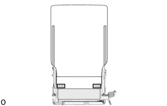
|
|
Fastening tape |
Attach the fastening tape.
73317
18.INSTALL REAR SEAT BELT CAP RH (w/ Seatback Board)
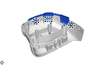
Attach the claw and guide and install the rear seat belt cap RH.
73C73E
19.INSTALL REAR NO. 2 SEAT SHOULDER BELT COVER RH (w/ Seatback Board)
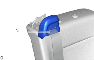
| *a | Slit |
Pass the rear seat outer 3 point type belt assembly RH through the slit of the rear No. 2 seat shoulder belt cover RH.
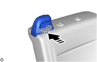
|
|
Install in this Direction |
Attach the guide and install the rear No. 2 seat shoulder belt cover RH as shown in the illustration.
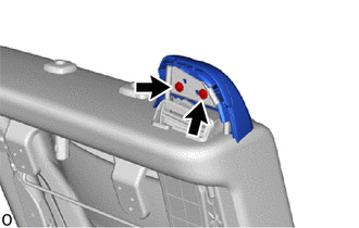
Install the 2 screws.
73C73D
20.INSTALL REAR NO. 1 SEAT SHOULDER BELT COVER RH (w/ Seatback Board)
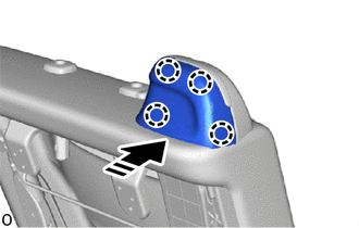
|
|
Install in this Direction |
Attach the claw and install the rear No. 1 seat shoulder belt cover RH as shown in the illustration.
71701A
21.INSTALL REAR SEATBACK BOARD SUB-ASSEMBLY RH (w/ Seatback Board)
Attach the guide and install the rear seatback board sub-assembly RH as shown in the illustration.
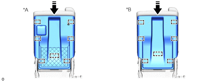
| *A | for Type A | *B | for Type B |
|
|
Install in this Direction | - | - |
74690A
22.INSTALL REAR SEAT ASSIST GRIP ASSEMBLY (w/ Seatback Board)
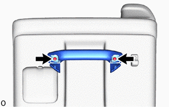
Install the rear seat assist grip assembly with the 2 screws.
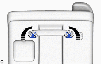
|
|
Install in this Direction |
Attach the claw and close the 2 covers as shown in the illustration.
72840J
23.INSTALL REAR SEAT ARMREST ASSEMBLY LH (w/ Armrest)
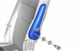
Attach the guide.
Install the rear seat armrest assembly LH with the 2 washers and the bolt.
- Torque:
- 33 N*m (337 kgf*cm, 24 ft.*lbf)
72848J
24.INSTALL NO. 1 SEAT ARMREST CAP (w/ Armrest)
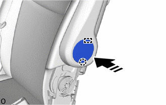
|
|
Install in this Direction |
Attach the guide and claw and install the No. 1 seat armrest cap as shown in the illustration.
71833M
25.INSTALL RH SEAT REAR NO. 2 SEAT RECLINING COVER RH
w/ Seatback Board:
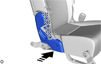
|
|
Install in this Direction |
Attach the guide and claw as shown in the illustration.
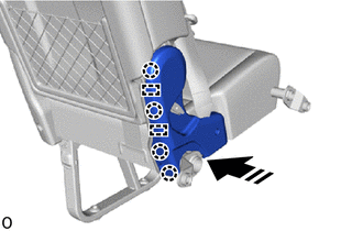
|
|
Install in this Direction |
Attach the guide and claw and install the RH seat rear No. 2 seat reclining cover RH as shown in the illustration.

Install the 2 screws.
w/o Seatback Board:
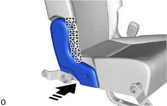
|
|
Install in this Direction |
Attach the guide and claw as shown in the illustration.
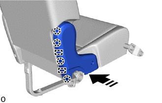
|
|
Install in this Direction |
Attach the guide and claw and install the RH seat rear No. 2 seat reclining cover RH as shown in the illustration.
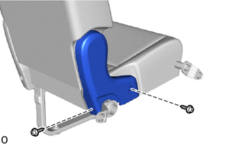
Install the 2 screws.
71834M
26.INSTALL RH SEAT REAR NO. 2 SEAT RECLINING COVER LH
w/ Seatback Board:
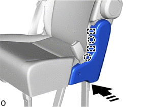
|
|
Install in this Direction |
Attach the guide and claw as shown in the illustration.
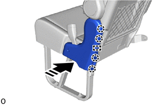
|
|
Install in this Direction |
Attach the guide and claw and install the RH seat rear No. 2 seat reclining cover LH as shown in the illustration.
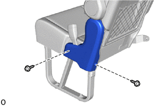
Install the 2 screws.
w/o Seatback Board:
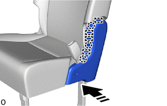
|
|
Install in this Direction |
Attach the guide and claw as shown in the illustration.
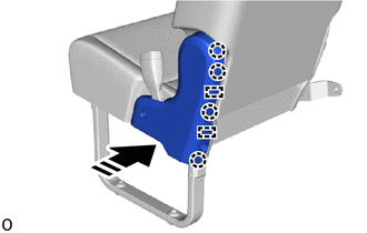
|
|
Install in this Direction |
Attach the guide and claw and install the RH seat rear No. 2 seat reclining cover LH as shown in the illustration.

Install the 2 screws.
72525R
27.INSTALL RECLINING ADJUSTER RELEASE HANDLE RH (w/ Seatback Board)
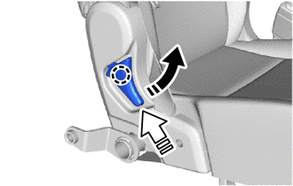
|
|
Lift in this Direction |

|
Install in this Direction |
Attach the claw and install the reclining adjuster release handle RH while lifting it up as shown in the illustration.
79967X
28.INSTALL REAR NO. 1 SEAT NO. 5 LEG SIDE COVER
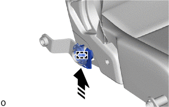
|
|
Install in this Direction |
Attach the hook as shown in the illustration.
Rotate the rear No. 1 seat No. 5 leg side cover as shown in the illustration.
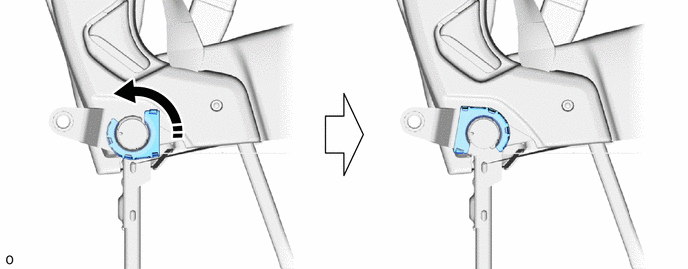
|
|
Rotate in this Direction | - | - |
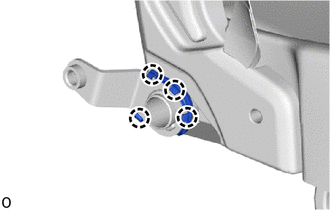
Attach the claw and install the rear No. 1 seat No. 5 leg side cover.
79967W
29.INSTALL REAR NO. 1 SEAT NO. 4 LEG SIDE COVER
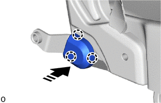
|
|
Install in this Direction |
Attach the claw and install the rear No. 1 seat No. 4 leg side cover as shown in the illustration.
79967U
30.INSTALL REAR NO. 1 SEAT NO. 2 LEG SIDE COVER (for Type B)
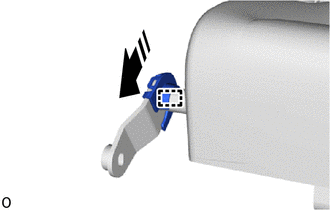
|
|
Install in this Direction |
Attach the hook as shown in the illustration.
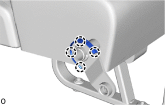
Attach the claw and install the rear No. 1 seat No. 2 leg side cover.
79967T
31.INSTALL REAR NO. 1 SEAT NO. 1 LEG SIDE COVER (for Type A)
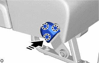
|
|
Install in this Direction |
Attach the claw and install the rear No. 1 seat No. 1 leg side cover as shown in the illustration.
79967V
32.INSTALL REAR NO. 1 SEAT NO. 3 LEG SIDE COVER
for Type A:
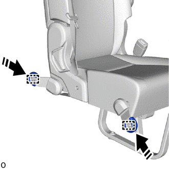
|
|
Install in this Direction |
Attach the hook and install the 2 rear No. 1 seat No. 3 leg side covers as shown in the illustration.
for Type B:
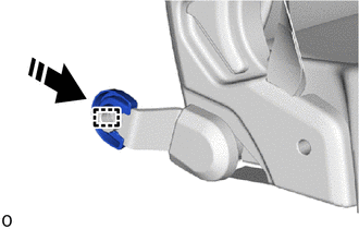
|
|
Install in this Direction |
Attach the hook and install the rear No. 1 seat No. 3 leg side cover as shown in the illustration.