SEAT REAR SEAT ASSEMBLY(for Van) REASSEMBLY
CAUTION / NOTICE / HINT
- CAUTION:
- ·
Wear protective gloves. Sharp areas on the parts may injure your hands.
·There is risk of injury.
PROCEDURE

 79180B
1.INSTALL NO. 1 SEATBACK SPRING ASSEMBLY RH
79180B
1.INSTALL NO. 1 SEATBACK SPRING ASSEMBLY RH
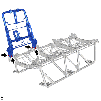
Temporarily install the No. 1 seatback spring assembly RH with the 4 bolts.
Tighten the 4 bolts in the order shown in the illustration.
- Torque:
- 42 N*m (428 kgf*cm, 31 ft.*lbf)
- NOTICE:
-
When tightening the bolts, do not apply any load to the No. 1 seatback spring assembly RH.
72569B
2.INSTALL SEATBACK STOPPER PLATE
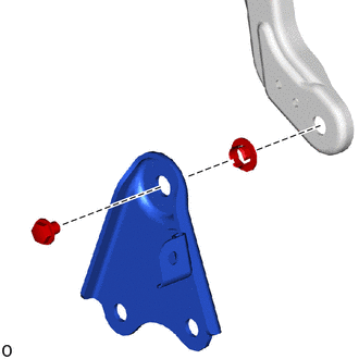
Install the bush and seatback stopper plate with the bolt.
- Torque:
- 14.5 N*m (148 kgf*cm, 11 ft.*lbf)
71802C
3.INSTALL RECLINING ADJUSTER COVER SUB-ASSEMBLY LH

|
Install in this Direction |
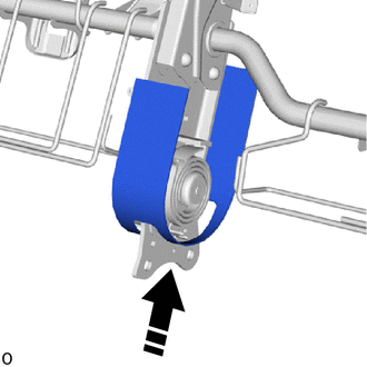
Install the center part of reclining adjuster cover sub-assembly LH as shown in the illustration.
79190
4.INSTALL NO. 1 SEATBACK SPRING ASSEMBLY LH

|
Bolt A |

|
Bolt B |
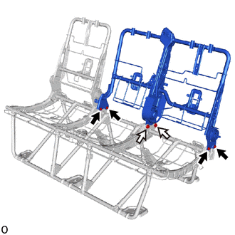
Temporarily install the No. 1 seatback spring assembly LH with the 6 bolts.
Tighten the 4 bolts A in the order shown in the illustration.
- Torque:
- 42 N*m (428 kgf*cm, 31 ft.*lbf)
- NOTICE:
-
When tightening the bolts, do not apply any load to the No. 1 seatback spring assembly LH.
Tighten the 2 bolts B in the order shown in the illustration.
- Torque:
- 94 N*m (959 kgf*cm, 69 ft.*lbf)
- NOTICE:
-
When tightening the bolts, do not apply any load to the No. 1 seatback spring assembly LH.
72570E
5.INSTALL NO. 1 SEAT RECLINING ADJUSTING CABLE ASSEMBLY RH
Set the No. 1 seat reclining adjusting cable assembly RH as shown in the illustration.
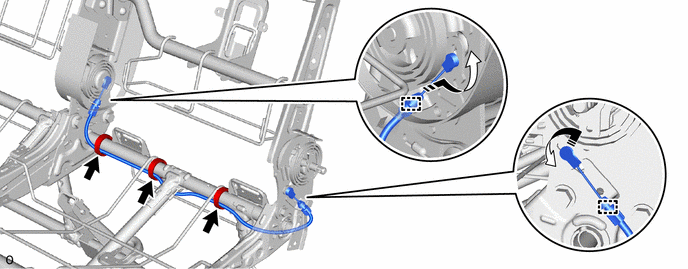
| *a | Pink | *b | Natural |
| *c | Locating Tape (Yellow) | *d | Locating Tape (White) |
| *e | Locating Tape (Orange) | - | - |
|
|
Wiring Harness Clamp |
|
Rotate in this Direction |
- NOTICE:
-
Make sure to set the No. 1 seat reclining adjusting cable assembly RH above the pipe.
Connect the cable ends and rotate them as shown in the illustration.
Attach the cable clamp.
Install the 3 wiring harness clamps.
- HINT:
-
Make sure to install the 3 wiring harness clamps on the location with locating tape.
71878H
6.INSTALL REAR SEAT INNER RECLINING COVER RH
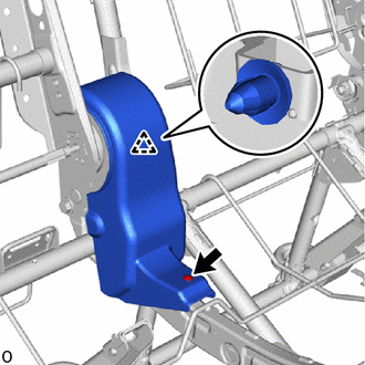
Attach the clip B.
Install the rear seat inner reclining cover RH with the clip A.
71879H
7.INSTALL REAR SEAT INNER RECLINING COVER LH
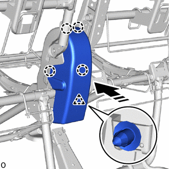
|
|
Install in this Direction |
Attach the claw and clip and install the rear seat inner reclining cover LH as shown in the illustration.
71873Y
8.INSTALL REAR SEAT LOWER CUSHION SHIELD
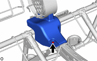
Install the rear seat lower cushion shield with the clip.
71874X
9.INSTALL REAR SEAT LOWER CUSHION SHIELD LH
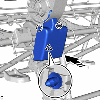
|
|
Install in this Direction |
Attach the claw and clip and install the rear seat lower cushion shield LH as shown in the illustration.
73373X
10.INSTALL NO. 1 SEAT NO. 1 SHOULDER BELT COVER LH
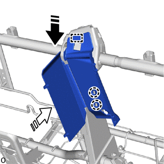
|
|
Install in this Direction (1) |

|
Install in this Direction (2) |
Attach the guide in the installation direction (1) shown in the illustration.
Attach the claw in the installation direction (2) shown in the illustration and install the No. 1 seat No. 1 shoulder belt cover LH.
73320A
11.INSTALL NO. 1 SEAT 3 POINT TYPE BELT ASSEMBLY LH
71802C
12.INSTALL RECLINING ADJUSTER COVER SUB-ASSEMBLY LH
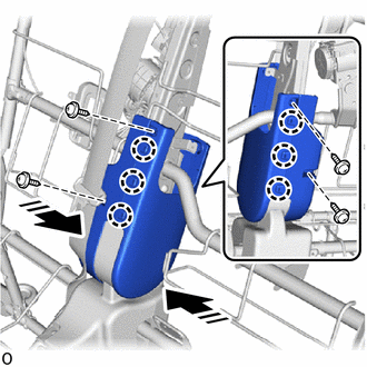
|
|
Install in this Direction |
Attach the claw and install the side parts of reclining adjuster cover sub-assembly LH.
Install the 4 screws.
71H76L
13.INSTALL RECLINING ADJUSTER INSIDE COVER
- HINT:
-
Use the same procedure for the other side.
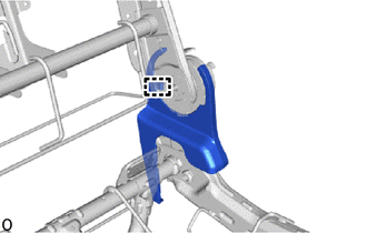
Attach the guide and install the reclining adjuster inside cover.
71H76M
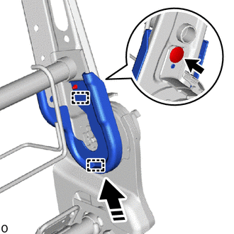
14.INSTALL RH SEAT RECLINING ADJUSTER INSIDE COVER
- HINT:
-
Use the same procedure for all RH seat reclining adjuster inside covers.
|
|
Install in this Direction |
Attach the guide as shown in the illustration.
Install the RH seat reclining adjuster inside cover with the clip.
71499M
15.INSTALL NO. 1 SEATBACK SPRING DAMPER LH
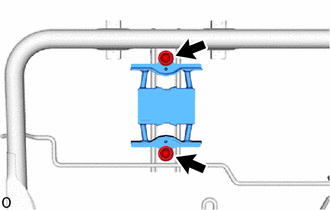
Install the No. 1 seatback spring damper LH with the 2 nuts.
- Torque:
- 14.5 N*m (148 kgf*cm, 11 ft.*lbf)
- HINT:
-
The No. 1 seatback spring damper LH can be installed to top and bottom whichever.
71499L
16.INSTALL NO. 1 SEATBACK SPRING DAMPER RH
- HINT:
-
Use the same procedure described for the LH side.
17.INSTALL SEAT COVER WIRE
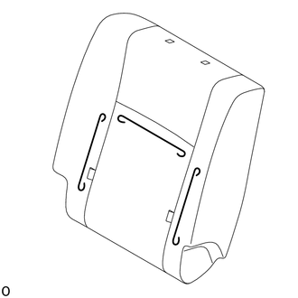
Install the seat cover wire.
- HINT:
- ·
Wire 1000 mm (3.28 ft.) or longer and shaped wire are available as supplied parts.
·For wire 1000 mm (3.28 ft.) or less in length, cut or shape 1000 mm (3.28 ft.) wire into the dimensions shown in the illustration.
·Make sure to read the precautions before preparing the wire.
- Dimensions:
A 220 mm (8.66 in.)
- HINT:
-
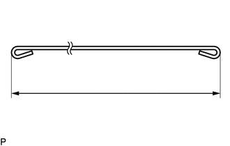
-
The dimensions shown in the illustration are the length.
79013D
18.INSTALL NO. 1 SEATBACK COVER SUB-ASSEMBLY RH
- HINT:
-
When installing a No. 1 seatback cover sub-assembly RH, refer to precaution in order to prevent wrinkles from forming.
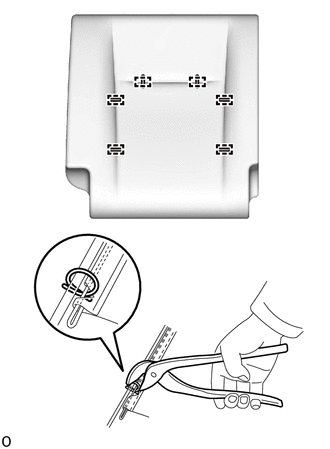
| *a | Hog Ring Pliers |
Using hog ring pliers, install the No. 1 seatback cover sub-assembly RH to the No. 1 seatback pad RH with 6 new hog rings in the order indicated in the illustration.
- NOTICE:
- ·
Be careful not to damage the No. 1 seatback cover sub-assembly RH.
·Be sure to securely install the hog rings as shown in the illustration while preventing wrinkles from forming on the No. 1 seatback cover sub-assembly RH.
19.INSTALL SEAT COVER WIRE
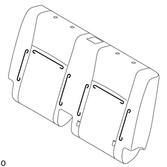
Install the seat cover wire.
- HINT:
- ·
Wire 1000 mm (3.28 ft.) or longer and shaped wire are available as supplied parts.
·For wire 1000 mm (3.28 ft.) or less in length, cut or shape 1000 mm (3.28 ft.) wire into the dimensions shown in the illustration.
·Make sure to read the precautions before preparing the wire.
- Dimensions:
A 220 mm (8.66 in.)
- HINT:
-
-
The dimensions shown in the illustration are the length.
79014B
20.INSTALL NO. 1 SEATBACK COVER SUB-ASSEMBLY LH
- HINT:
-
When installing a No. 1 seatback cover sub-assembly LH, refer to precaution in order to prevent wrinkles from forming.
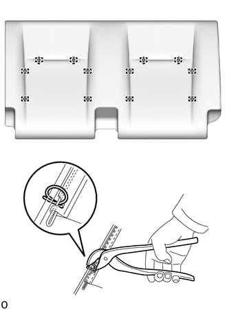
| *a | Hog Ring Pliers |
Using hog ring pliers, install the No. 1 seatback cover sub-assembly LH to the No. 1 seatback pad LH with 12 new hog rings in the order indicated in the illustration.
- NOTICE:
- ·
Be careful not to damage the No. 1 seatback cover sub-assembly LH.
·Be sure to securely install the hog rings as shown in the illustration while preventing wrinkles from forming on the No. 1 seatback cover sub-assembly LH.
21.INSTALL REAR SEATBACK COVER WITH PAD LH
Install the rear seatback cover with pad LH.
22.INSTALL REAR SEATBACK COVER WITH PAD RH
Install the rear seatback cover with pad RH.
71930Q
23.INSTALL REAR SEAT HEADREST SUPPORT ASSEMBLY
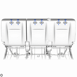
Attach the claw and install the 6 rear seat headrest support assemblies.
Close the 4 fasteners and insert them as shown in the illustration.
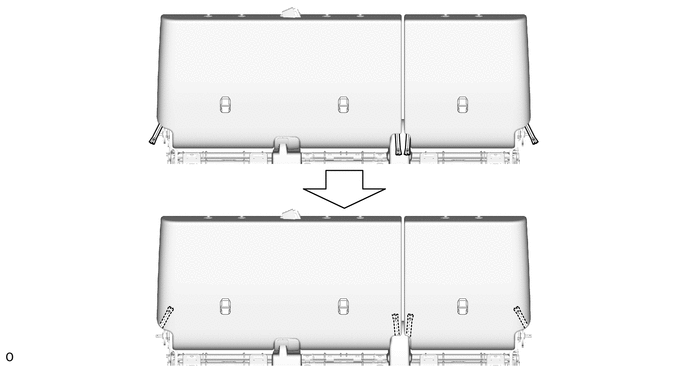
Attach the hook.
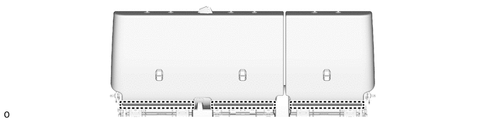
73375
24.INSTALL REAR SEAT SHOULDER BELT COVER LH
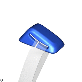
| *a | Slit |
Pass the belt through the slit.
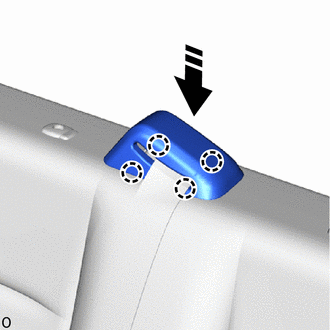
|
|
Install in this Direction |
Attach the claw and install the rear seat shoulder belt cover LH as shown in the illustration.
72996J
25.INSTALL NO. 2 REAR SEATBACK COVER
- HINT:
-
Use the same procedure for the RH side.
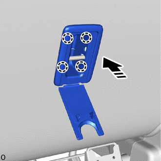
|
|
Install in this Direction |
Attach the claw and install the No. 2 rear seatback cover as shown in the illustration.
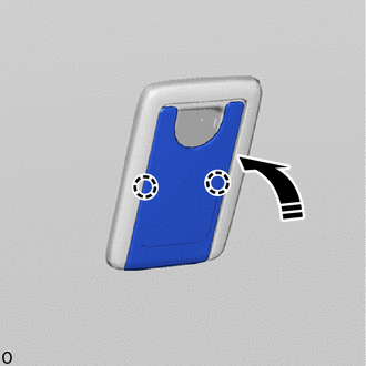
|
|
Close in this Direction |
Attach the claw and close the cover as shown in the illustration.
72996H
26.INSTALL REAR SEATBACK COVER (w/ Center Bracket)
- HINT:
-
Use the same procedure described for the No. 2 rear seatback cover.
73380D
27.INSTALL REAR SEAT INNER BELT ASSEMBLY (for RH Side)
73380A
28.INSTALL REAR CENTER SEAT INNER BELT ASSEMBLY
73380D
29.INSTALL REAR SEAT INNER BELT ASSEMBLY (for LH Side)
30.INSTALL SEAT COVER WIRE
Install the seat cover wire.
- HINT:
- ·
Wire 1000 mm (3.28 ft.) or longer and shaped wire are available as supplied parts.
·For wire 1000 mm (3.28 ft.) or less in length, cut or shape 1000 mm (3.28 ft.) wire into the dimensions shown in the illustration.
·Make sure to read the precautions before preparing the wire.

- Dimensions:
A 110 mm (4.33 in.) B 240 mm (9.45 in.) C 320 mm (1.05 ft.) - -
- HINT:
-
-
The dimensions shown in the illustration are the length.
79011E
31.INSTALL NO. 1 SEAT CUSHION COVER SUB-ASSEMBLY
- HINT:
-
When installing a No. 1 seat cushion cover sub-assembly, refer to precaution in order to prevent wrinkles from forming.
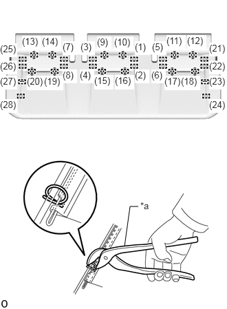
| *a | Hog Ring Pliers |
Using hog ring pliers, install the No. 1 seat cushion cover sub-assembly to the No. 1 seat cushion pad with 28 new hog rings in the order indicated in the illustration.
- NOTICE:
- ·
Be careful not to damage the No. 1 seat cushion cover sub-assembly.
·Be sure to securely install the hog rings as shown in the illustration while preventing wrinkles from forming on the No. 1 seat cushion cover sub-assembly.
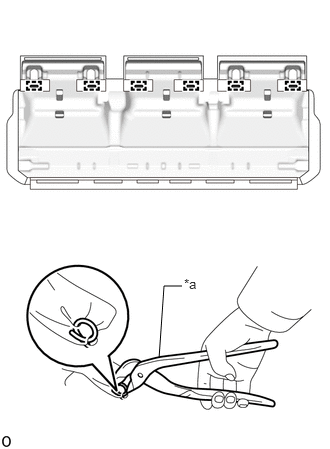
| *a | Hog Ring Pliers |
Using hog ring pliers, install 6 new hog rings.
- NOTICE:
-
Be careful not to damage the No. 1 seat cushion cover sub-assembly.
32.INSTALL SEAT CUSHION COVER WITH PAD
Set the seat cushion cover with pad.
w/ Seat Belt Warning System:
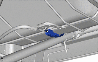
Attach the claw and install the connector of occupant detection sensor.
- HINT:
-
Use the same procedure for the other sides.
Connect the 3 connectors.

Attach the hook.

Attach the hook and fastening tape.


|
Fastening Tape | - | - |
73340
33.INSTALL REAR SEAT LAP TYPE BELT ASSEMBLY LH
73330
34.INSTALL REAR SEAT LAP TYPE BELT ASSEMBLY RH
- HINT:
-
Use the same procedure described for the LH side.
71834J
35.INSTALL NO. 1 SEAT OUTER NO. 1 RECLINING COVER LH
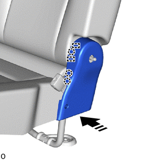
|
|
Install in this Direction |
Attach the claw as shown in the illustration.
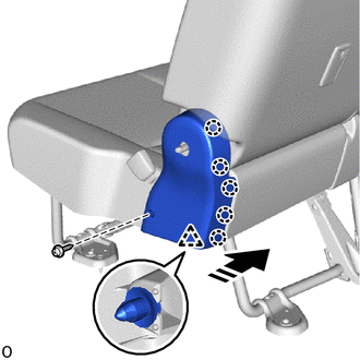
|
|
Install in this Direction |
Attach the clip and claw as shown in the illustration.
Install the No. 1 seat outer No. 1 reclining cover LH with the screw.
71833K
36.INSTALL NO. 1 SEAT OUTER NO. 1 RECLINING COVER RH
- HINT:
-
Use the same procedure described for the LH side.
72526L
37.INSTALL RECLINING ADJUSTER RELEASE HANDLE LH
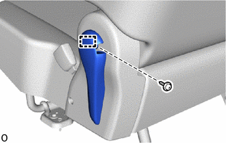
Attach the guide and install the reclining adjuster release handle LH.
Install the screw.
72525N
38.INSTALL NO. 1 SEAT RECLINING ADJUSTER RELEASE HANDLE RH
- HINT:
-
Use the same procedure described for the reclining adjuster release handle LH.
72329G
39.INSTALL REAR NO. 2 SEAT ADJUSTER BOLT COVER
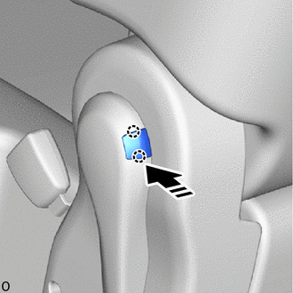
|
|
Install in this Direction |
Attach the claw and install the rear No. 2 seat adjuster bolt cover as shown in the illustration.
72329F
40.INSTALL REAR SEAT ADJUSTER BOLT COVER
- HINT:
-
Use the same procedure described for the rear No. 2 seat adjuster bolt cover.