LIGHTING (INT) BACK DOOR COURTESY SWITCH INSTALLATION
PROCEDURE

 69350P
1.INSTALL BACK DOOR LOCK ASSEMBLY WITH COURTESY LIGHT SWITCH (w/o Easy Closer)
69350P
1.INSTALL BACK DOOR LOCK ASSEMBLY WITH COURTESY LIGHT SWITCH (w/o Easy Closer)
Apply MP grease to the sliding parts of the back door lock assembly with courtesy light switch.
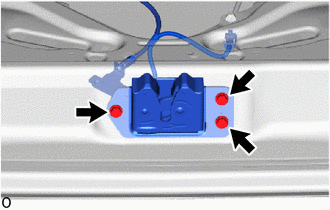
Install the back door lock assembly with courtesy light switch with the 3 bolts.
- Torque:
- 12.5 N*m (127 kgf*cm, 9 ft.*lbf)
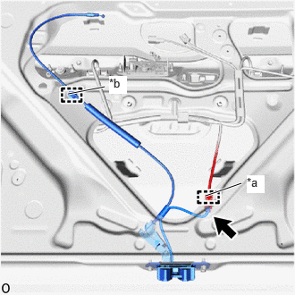
| *a | Wire harness Clamp |
| *b | Cable Clamp |
Attach the wire harness clamp and cable clamp.
Connect the connector.
69350P
2.INSTALL BACK DOOR LOCK ASSEMBLY WITH COURTESY LIGHT SWITCH (w/ Easy Closer)
Apply MP grease to the sliding parts of the back door lock assembly with courtesy light switch.
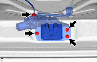
Install the back door lock assembly with courtesy light switch with the 4 bolts.
- Torque:
- 12.5 N*m (127 kgf*cm, 9 ft.*lbf)
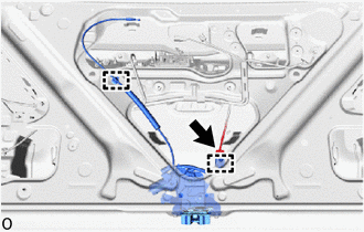
Attach the cable clamp.
Connect the connector.
69690
3.INSTALL BACK DOOR REMOTE CONTROL ASSEMBLY
Apply MP grease to the sliding areas of the back door remote control assembly.
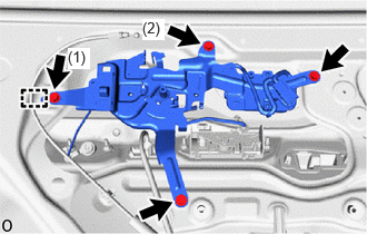
Attach the guide.
Install the back door remote control assembly with the 4 screws in the order shown in the illustration.
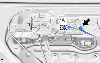
| *A | w/ Illumination |
w/ Illumination
Attach the connector clamp.
Connect the connector.
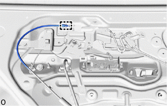
Attach the clamp and connect the back door lock cable.
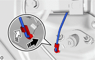

|
Install in this Direction (1) |

|
Install in this Direction (2) |
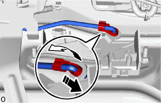
Connect the back door cylinder to lock control link in the direction indicated by the arrow (1) in the illustration.
Attach the snap in the direction indicated by the arrow (2) in the illustration.
|
|
Install in this Direction (1) |
|
|
Install in this Direction (2) |
Connect the back door lock open link in the direction indicated by the arrow (1) in the illustration.
Attach the snap in the direction indicated by the arrow (2) in the illustration.
67751
4.INSTALL BACK DOOR TRIM BOARD
67961A
5.INSTALL BACK DOOR PULL STRAP
69783B
6.INSTALL BACK DOOR INSIDE HANDLE BEZEL (w/ Handle, w/o Illumination)
69783B
7.INSTALL BACK DOOR INSIDE HANDLE BEZEL (w/ Handle, w/ Illumination)
69291
8.INSTALL BACK DOOR INSIDE HANDLE ASSEMBLY (w/ Handle)
69298
9.INSTALL BACK DOOR INSIDE HANDLE COVER (w/ Handle, w/ Cover)
10.CHECK BACK DOOR CLOSER SYSTEM (w/ Easy Closer)