RM35X0E
_59
Vehicle Exterior
_078503
DOOR / HATCH
_0381019
BACK DOOR CLOSER SYSTEM
U
DOOR / HATCH BACK DOOR CLOSER SYSTEM TERMINALS OF ECU
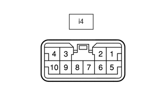
CHECK BACK DOOR CLOSER RELAY
a.
1.427,0.292 1.917,0.604
0.49,0.313
1.615,0.354 2.073,0.552
0.458,0.198
10
false
i4
Disconnect the back door closer relay connector.
b.
Measure the voltage and resistance according to the value(s) in the table below.
| Tester Connection | Wiring Color | Terminal Description | Condition | Specified Condition |
|---|---|---|---|---|
| i4-5 (B) - Body ground | W - Body ground | Power supply | Always | 11 to 14 V |
| i4-7 (GND) - Body ground | W-B - Body ground | Ground | Always | Below 1 Ω |
| i4-4 (HAF) - i4-8 (SGND) | W - G | Half/full latch switch input | Back door fully open → half latched | Below 1 Ω → 10 kΩ or higher |
| i4-3 (FUL) - i4-8 (SGND) | L - G | Courtesy switch input | Back door open → fully closed | Below 1 Ω → 10 kΩ or higher |
c.
Reconnect the i4 back door closer relay connector.
d.
Measure the voltage and resistance according to the value(s) in the table below.
| Tester Connection | Wiring Color | Terminal Description | Condition | Specified Condition |
|---|---|---|---|---|
| i4-1 (DC-) - i4-8 (SGND) | R - G | Back door closer output (release rotation) | Back door fully open → half latched → close rotation → release rotation → operation finished | Below 1 V → Below 1 V → Below 1 V → 11 to 14 V → Below 1 V |
| i4-2 (DC+) - i4-8 (SGND) | L - G | Back door closer output (close rotation) | Back door fully open → half latched → close rotation → release rotation → operation finished | Below 1 V → Below 1 V → 11 to 14 V → Below 1 V → Below 1 V |
| i4-8 (SGND) - Body ground | G - Body ground | Ground | Always | Below 1 Ω |
| i4-10 (POS) - i4-8 (SGND) | GR - G | Initial position switch input | Back door fully open → half latched → close rotation → release rotation → operation finished | 11 to 14 V → 11 to 14 V → Below 1 V → Below 1 V → 11 to 14 V |