DOOR / HATCH BACK DOOR(except Wagon) DISASSEMBLY
CAUTION / NOTICE / HINT
The necessary procedures (adjustment, calibration, initialization, or registration) that must be performed after parts are removed and installed, or replaced during slide door motor unit removal/installation are shown below.
| Replaced Part or Performed Procedure | Effect/Inoperative Function when Necessary Procedure not Performed | Necessary Procedure | Link |
|---|---|---|---|
| Television camera assembly (Including removal and installation) | ·
Parking assist monitor system initialization ·
Television camera assembly optical axis (Back camera position setting) |
Parking assist monitor system | ( 201902,202310,_56,_079315,_0385736,RM100000001GNRB,202310,999999,_56,_079315,_0385736,RM100000002G5JM,) 201902,202310,_56,_079315,_0385736,RM100000001GNRB,202310,999999,_56,_079315,_0385736,RM100000002G5JM,)
|
| Television camera view adjustment (Rear adjustment) | Panoramic view monitor system | (201906,202310,_56,_079315,_0396274,RM100000001IGR4,202310,999999,_56,_079315,_0396274,RM100000002G5L7,)
|
PROCEDURE

 67760A
1.REMOVE BACK DOOR UPPER TRIM BOARD ASSEMBLY (for Regular)
67760A
1.REMOVE BACK DOOR UPPER TRIM BOARD ASSEMBLY (for Regular)
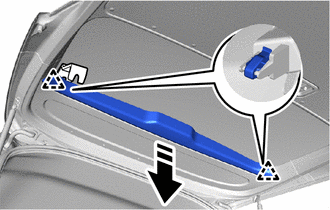

|
Remove in this Direction |
Using moulding remover B, pull in the direction of the arrow and detach the clip.
w/o Rear Wiper:
Place your hand at the position shown in the illustration, and while pulling the back door upper trim board assembly toward you, detach the clip and remove the back door upper trim board assembly.
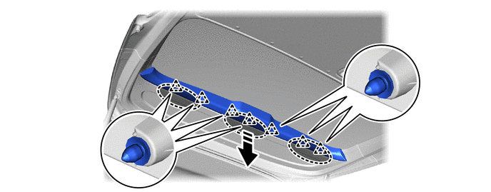

|
Place Hand Here |
|
Remove in this Direction |
w/ Rear Wiper:
Place your hand at the position shown in the illustration, and while pulling the back door upper trim board assembly toward you, detach the clip and remove the back door upper trim board assembly.
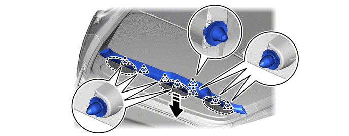
|
|
Place Hand Here |
|
Remove in this Direction |
67760A
2.REMOVE BACK DOOR UPPER TRIM BOARD ASSEMBLY (for Large)
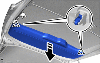
|
|
Remove in this Direction |
Using moulding remover B, pull in the direction of the arrow and detach the clip.
Place your hand at the position shown in the illustration, and while pulling the back door upper trim board assembly toward you, detach the clip.
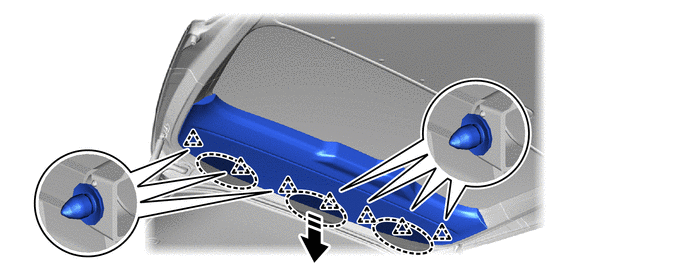
|
|
Place Hand Here |
|
Remove in this Direction |
Detach the clip and remove the back door upper trim board assembly as shown in the illustration.
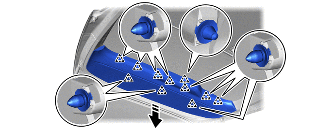
|
|
Remove in this Direction | - | - |
69298
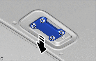
3.REMOVE BACK DOOR INSIDE HANDLE COVER (w/ Handle, w/ Cover)
|
|
Remove in this Direction |
Detach the claw in the direction indicated by the arrow shown in the illustration to remove the back door inside handle cover.
69291
4.REMOVE BACK DOOR INSIDE HANDLE ASSEMBLY (w/ Handle)
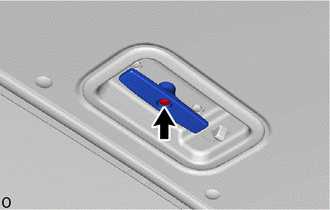
Remove the screw and back door inside handle assembly.
69783B
5.REMOVE BACK DOOR INSIDE HANDLE BEZEL (w/ Handle, w/o Illumination)
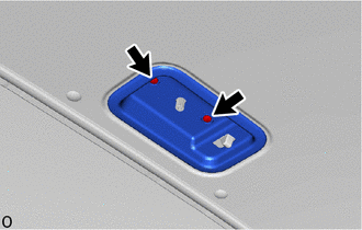
Remove the 2 screws and back door inside handle bezel.
69783B
6.REMOVE BACK DOOR INSIDE HANDLE BEZEL (w/ Handle, w/ Illumination)
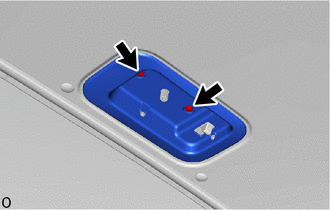
Remove the 2 screws.
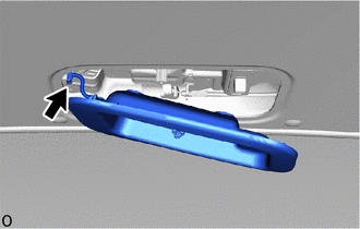
Disconnect the connector and remove the back door inside handle bezel sub-assembly.
67961A
7.REMOVE BACK DOOR PULL STRAP
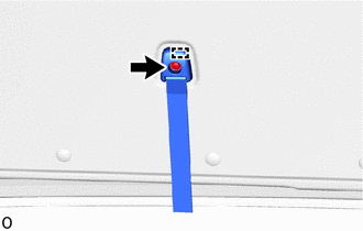
Remove the screw.
Detach the guide and remove the back door pull strap.
67751
8.REMOVE BACK DOOR TRIM BOARD
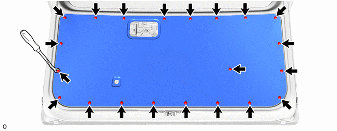
Using a clip remover with its tip wrapped with protective tape, remove the 21 clips and back door trim board.

|
Protective Tape | - | - |
9.REMOVE REAR WIPER ARM AND BLADE ASSEMBLY (w/ Rear Wiper)
85110R
10.REMOVE REAR WIPER MOTOR ASSEMBLY (w/ Rear Wiper)
85143R
11.REMOVE REAR WIPER MOTOR GROMMET (w/ Rear Wiper)
85035R
12.REMOVE REAR WASHER NOZZLE SUB-ASSEMBLY (w/ Rear Wiper)
67290
13.REMOVE BACK DOOR DAMPER ASSEMBLY (w/ Damper)
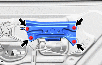
Remove the 4 bolts.
Detach the guide and remove the back door damper assembly.
69690
14.REMOVE BACK DOOR REMOTE CONTROL ASSEMBLY
69350P
15.REMOVE BACK DOOR LOCK ASSEMBLY WITH COURTESY LIGHT SWITCH (w/o Easy Closer)
69350P
16.REMOVE BACK DOOR LOCK ASSEMBLY WITH COURTESY LIGHT SWITCH (w/ Easy Closer)
85976
17.REMOVE BACK DOOR CLOSER RELAY (w/ Easy Closer)
18.REMOVE BACK DOOR LOCK CYLINDER ASSEMBLY
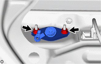
Remove the 2 nuts and back door lock cylinder assembly.
69211C
19.REMOVE BACK DOOR OUTSIDE HANDLE
|
|
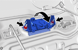
Remove in this Direction |
Remove the 2 nuts and back door outside handle as shown in the illustration.
76801
20.REMOVE BACK DOOR OUTSIDE GARNISH SUB-ASSEMBLY
81270
21.REMOVE LICENSE PLATE LIGHT ASSEMBLY
- HINT:
-
Use the same procedure for the RH and LH sides.
76839C
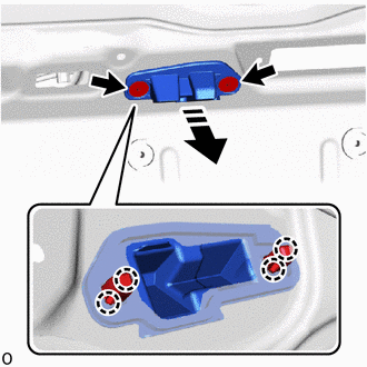
22.REMOVE BACK DOOR GARNISH COVER (w/o Rear View Monitor System)
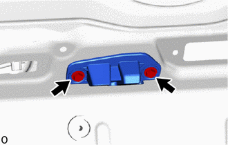
Remove the 2 screws.
|
|
Remove in this Direction |
Using pliers, grip the claw of the 2 screw grommets and slide the 2 screw grommets to remove the back door garnish cover and 2 screw grommets as shown in the illustration.
86790
23.REMOVE TELEVISION CAMERA ASSEMBLY (w/ Rear View Monitor System)
867C0
24.REMOVE INNER MIRROR CAMERA ASSEMBLY (w/ Digital Inner Mirror)
25.REMOVE CAMERA CLEANER NOZZLE ASSEMBLY (w/ Digital Inner Mirror)
81570
26.REMOVE CENTER STOP LIGHT ASSEMBLY
68960
27.REMOVE BACK DOOR STAY ASSEMBLY LH
68950C
28.REMOVE BACK DOOR STAY ASSEMBLY RH
- HINT:
-
Use the same procedure described for the LH side.
68946
29.REMOVE BACK DOOR UPPER DAMPER STAY BRACKET LH
68945
30.REMOVE BACK DOOR UPPER DAMPER STAY BRACKET RH
- HINT:
-
Use the same procedure described for the LH side.
68948
31.REMOVE BACK DOOR LOWER DAMPER STAY BRACKET LH
68947
32.REMOVE BACK DOOR LOWER DAMPER STAY BRACKET RH
- HINT:
-
Use the same procedure described for the LH side.
87950
33.REMOVE OUTER UNDER REAR VIEW MIRROR ASSEMBLY (w/ Outer Under Rear View Mirror)
67207C
34.REMOVE BACK DOOR STOPPER SUB-ASSEMBLY (w/ Bracket)
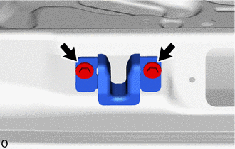
Remove the 2 bolts and back door stopper sub-assembly.
69404A
35.REMOVE BACK DOOR SIDE FEMALE STOPPER SUB-ASSEMBLY LH (w/ Bracket)
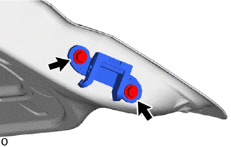
Remove the 2 bolts and back door side female stopper sub-assembly LH.
69403A
36.REMOVE BACK DOOR SIDE FEMALE STOPPER SUB-ASSEMBLY RH (w/ Bracket)
- HINT:
-
Use the same procedure described for the LH side.
67282
37.REMOVE BACK DOOR NO. 1 STOPPER (w/o Bracket)
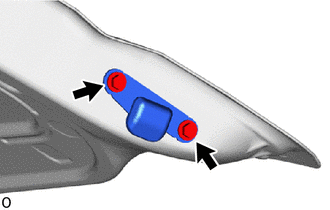
Remove the 2 bolts and back door No. 1 stopper.
67281F
38.REMOVE BACK DOOR LOWER STOPPER (w/o Bracket)
- HINT:
-
Use the same procedure described for the back door No. 1 stopper.
69359
39.REMOVE BACK DOOR LOCK CUSHION
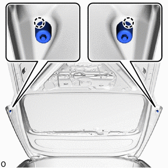
Detach the claw and remove the 2 back door lock cushions.
67837L
40.REMOVE DOOR DUST PROOF SEAL
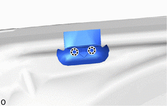
Detach the claw and remove the door dust proof seal.
- HINT:
-
Use the same procedure for the RH and LH sides.