DRIVE SHAFT / PROPELLER SHAFT FRONT DRIVE SHAFT ASSEMBLY(for HEV Model) REASSEMBLY
CAUTION / NOTICE / HINT
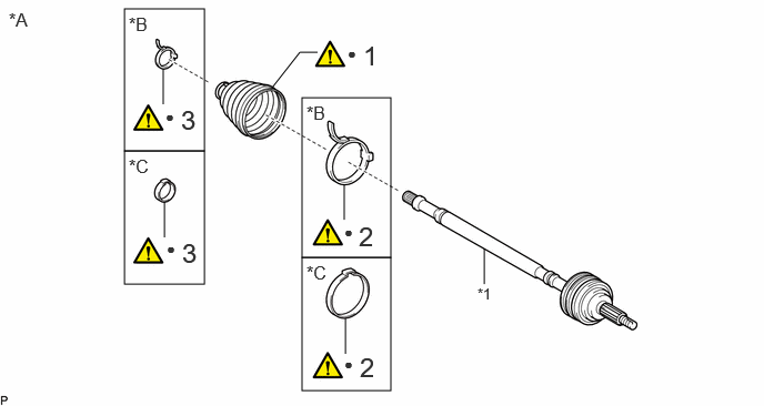
| Procedure | Part Name Code | 
|

|

|
|
|---|---|---|---|---|---|
| 1 | FRONT AXLE OUTBOARD JOINT BOOT | - | ( 202307,999999,_52,_112266,_0604511,RM100000002C7Q0_04_0002,) 202307,999999,_52,_112266,_0604511,RM100000002C7Q0_04_0002,)
|
- | - |
| 2 | FRONT NO. 2 AXLE OUTBOARD JOINT BOOT CLAMP | 43447F | (202307,999999,_52,_112266,_0604511,RM100000002C7Q0_04_0003,)
|
- | - |
| 3 | FRONT AXLE OUTBOARD JOINT BOOT CLAMP | 43447E | (202307,999999,_52,_112266,_0604511,RM100000002C7Q0_04_0003,)
|
- | - |
| *A | for LH Side | *B | for Type A |
| *C | for Type B | - | - |
| *1 | FRONT DRIVE OUTBOARD JOINT SHAFT ASSEMBLY | - | - |
| ● | Non-reusable part | - | - |
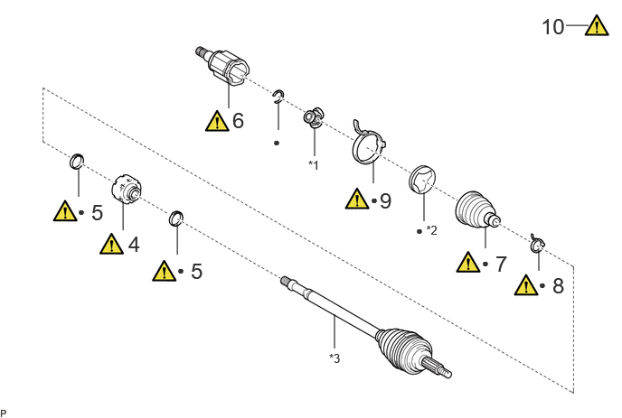
| Procedure | Part Name Code |
|
|
|
|
|---|---|---|---|---|---|
| 4 | FRONT DRIVE SHAFT DAMPER | 43474E | (202307,999999,_52,_112266,_0604511,RM100000002C7Q0_04_0005,)
|
- | - |
| 5 | FRONT DRIVE SHAFT DAMPER CLAMP | 43474G | (202307,999999,_52,_112266,_0604511,RM100000002C7Q0_04_0013,)
|
- | - |
| 6 | FRONT DRIVE INBOARD JOINT ASSEMBLY | 43040 | (202307,999999,_52,_112266,_0604511,RM100000002C7Q0_04_0012,)
|
- | - |
| 7 | FRONT AXLE INBOARD JOINT BOOT | - | (202307,999999,_52,_112266,_0604511,RM100000002C7Q0_04_0014,)
|
- | - |
| 8 | FRONT AXLE INBOARD JOINT BOOT CLAMP | 43448F | (202307,999999,_52,_112266,_0604511,RM100000002C7Q0_04_0010,)
|
- | - |
| 9 | FRONT NO. 2 AXLE INBOARD JOINT BOOT CLAMP | 43448G | (202307,999999,_52,_112266,_0604511,RM100000002C7Q0_04_0010,)
|
- | - |
| 10 | INSPECT FRONT DRIVE SHAFT ASSEMBLY | 43420 | (202307,999999,_52,_112266,_0604511,RM100000002C7Q0_04_0011,)
|
- | - |
| *1 | TRIPOD JOINT | *2 | FRONT AXLE INBOARD JOINT GROMMET |
| *3 | FRONT DRIVE OUTBOARD JOINT SHAFT ASSEMBLY | - | - |
| ● | Non-reusable part | - | - |
CAUTION / NOTICE / HINT
- NOTICE:
- ·
Secure the drive shaft in a vise between aluminum plates.
·Do not overtighten the vise.
- HINT:
- ·
Use the same procedure for the RH side and LH side.
·The following procedure is for the LH side.
PROCEDURE

 1.INSTALL FRONT AXLE OUTBOARD JOINT BOOT (for LH Side)
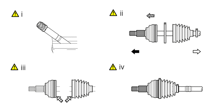

|
Outboard Joint Side | 
|
Inboard Joint Side |

|
Parts insertion direction | 
|
Grease |
Wrap the splines of the front drive outboard joint shaft assembly with protective tape to prevent the boot from being damaged.
Install new parts to the front drive outboard joint shaft assembly in the following order:
1. Front No. 2 axle outboard joint boot clamp
2. Front axle outboard joint boot
3. Front axle outboard joint boot clamp
Pack the joint portion of the front drive outboard joint shaft assembly and front axle outboard joint boot with grease.
- Standard Grease Capacity:
86 to 96 g (3.03 to 3.39 oz.)
Install the front axle outboard joint boot to the front drive outboard joint shaft assembly groove.
- NOTICE:
- ·
Do not allow grease to adhere to the boot clamp track of the outboard joint boot.
·Keep the inside of the outboard joint boot free of foreign matter.
43447F
2.INSTALL FRONT NO. 2 AXLE OUTBOARD JOINT BOOT CLAMP (for LH Side)
|
|
|
for Type A:
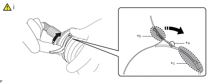
| *a | Fulcrum Point | *b | Lever Push Position |
| *c | Band Support Position | - | - |

|
Turn | - | - |
Install the front No. 2 axle outboard joint boot clamp to the front axle outboard joint boot and temporarily fold back the lever at the fulcrum point.
- NOTICE:
- ·
Set the lever to the guide groove correctly and install the clamp as far to the inside of the vehicle as possible.
·Check the band and the lever for any deformation before folding back the lever.
·The lever folds easily at the fulcrum point when pushed at the position shown in the illustration.
·When folding back the lever, do not push at the end of the lever.
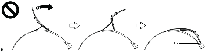 6.771,1.49 6.125,1.49 true 5.948,1.417 6.26,1.573 0.313,0.156 10 false *a
*a Temporary Claw - -
·If the lever bends in the middle, it may not engage with the temporary claws or may not be held in the correct position.
for Type A:
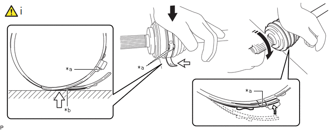
| *a | Temporary Claw | *b | Fulcrum Point |
|
|
Press down |
|
Contact Point |
|
|
Turn | 
|
Install in this Direction |
As shown in the illustration, while pressing the outboard joint area against the work surface, firmly press the lever into place by rolling the outboard joint area forward from the folded fulcrum point to the temporary claw area until a click sound is heard.
- NOTICE:
- ·
Do not damage the deflector.
·Make sure that the outboard joint is in direct contact with the work surface.
for Type A:
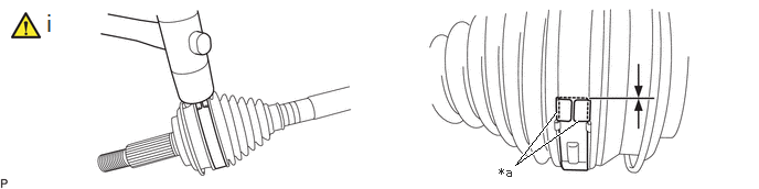
| *a | Buckle | - | - |
Using a plastic hammer, tap the buckle to secure it while adjusting the clearance between the lever and the groove to make the clearance between the buckle edge and the lever end even.
- NOTICE:
- ·
Do not use excessive force when tapping with the plastic hammer.
·Do not damage the front axle outboard joint boot.
for Type B:
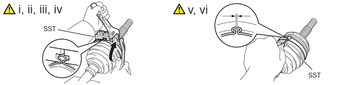
Install the front No. 2 axle outboard joint boot clamp to the front axle outboard joint boot.
Place SST onto the front No. 2 axle outboard joint boot clamp, press it against the boot and slightly tighten SST.
- SST
- 09521-24010
Tighten SST so that the front No. 2 axle outboard joint boot clamp is pinched.
- NOTICE:
-
Do not overtighten SST.
Remove SST.
Using SST, measure the clearance of the front No. 2 axle outboard joint boot clamp.
- SST
- 09240-00021
- Clearance:
0.5 to 1.5 mm (0.0197 to 0.0591 in.)
If the clearance is not as specified, retighten SST.
43447E
3.INSTALL FRONT AXLE OUTBOARD JOINT BOOT CLAMP (for LH Side)
|
|
|
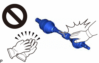
for Type A:
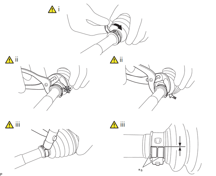
| *a | Buckle | - | - |
|
|
Turn |
|
Install in this Direction |

|
Place the tip near the center of the lever | - | - |
Install the front axle outboard joint boot clamp to the front axle outboard joint boot and provisionally bend the lever.
- NOTICE:
- ·
Set the lever into the guide groove correctly.
·Check the band and lever for any deformation before bending the lever.
Using water pump pliers, pinch the front axle outboard joint boot clamp to provisionally fix it.
Using a plastic hammer, tap the buckle to fix it while adjusting the clearance between the lever and groove to make the clearances between the buckle edge and lever end even.
- NOTICE:
-
Do not damage the front axle outboard joint boot.
for Type B:
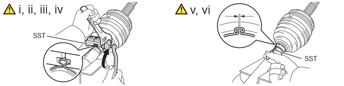
Install the front axle outboard joint boot clamp to the front axle outboard joint boot.
Place SST onto the front axle outboard joint boot clamp, press it against the boot and slightly tighten SST.
- SST
- 09521-24010
Tighten SST so that the front axle outboard joint boot clamp is pinched.
- NOTICE:
-
Do not overtighten SST.
Remove SST.
Using SST, measure the clearance of the front axle outboard joint boot clamp.
- SST
- 09240-00021
- Clearance:
0.5 to 1.5 mm (0.0197 to 0.0591 in.)
If the clearance is not as specified, retighten SST.
43474E
4.INSTALL FRONT DRIVE SHAFT DAMPER
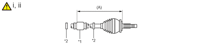
| *1 | Front Drive Shaft Damper | *2 | Front Drive Shaft Damper Clamp |
Temporarily install the front drive shaft damper and 2 new front drive shaft damper clamps to the front drive outboard joint shaft assembly as shown in the illustration.
Set the dimension (A) as specified below.
- Dimension (A):
for LH Side 211.7 to 215.7 mm (8.33 to 8.49 in.) for RH Side 488 to 492 cm (1.60 to 1.61 ft.)
43474G
5.INSTALL FRONT DRIVE SHAFT DAMPER CLAMP
for Type A:
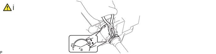
| *a | Claw | - | - |
Using needle-nose pliers, install the 2 front drive shaft damper clamps as shown in the illustration.
- NOTICE:
- ·
Be sure to install the clamps in the correct position.
·Do not damage the front drive shaft damper.
for Type B:
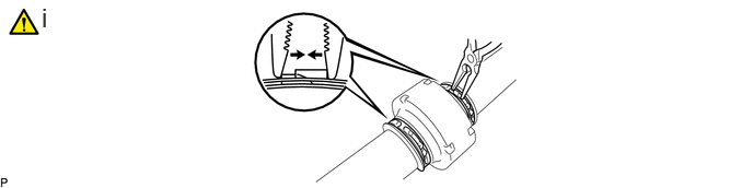
Using needle-nose pliers, install the 2 front drive shaft damper clamps as shown in the illustration.
- NOTICE:
- ·
Be sure to install the clamps in the correct position.
·Do not damage the front drive shaft damper.
43040
6.INSTALL FRONT DRIVE INBOARD JOINT ASSEMBLY
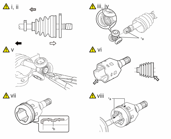
| *a | Matchmark | *b | Groove |
|
|
Outboard Joint Side |
|
Inboard Joint Side |
|
|
Parts insertion direction |
|
Grease |
Install new parts to the front drive outboard joint shaft assembly in the following order:
1. Front axle inboard joint boot clamp
2. Front axle inboard joint boot
3. Front No. 2 axle inboard joint boot clamp
Remove the protective tape.
Align the matchmarks and install the tripod joint to the front drive outboard joint shaft assembly.
- NOTICE:
-
Face the serrated side of the tripod joint outward and install it to the outboard joint end.
Using a brass bar and a hammer, install the tripod joint to the front drive outboard joint shaft assembly.
- NOTICE:
- ·
Do not tap the rollers.
·Keep the tripod joint free of foreign matter.
·Be sure to install the tripod joint in the correct direction.
Using a snap ring expander, install a new shaft snap ring to the front drive outboard joint shaft assembly.
Pack the front drive inboard joint assembly and front axle inboard joint boot with grease.
- Standard Grease Capacity:
168 to 178 g (5.93 to 6.28 oz.)
Install a new front axle inboard joint grommet to the front drive inboard joint assembly.
- NOTICE:
- ·
Align the phase of the protrusions and depressions, and assemble the front axle inboard joint grommet to the front drive inboard joint assembly.
·Make sure the protrusion on the inner corner of the front axle inboard joint grommet is securely inserted into the groove in the outer surface of the joint.
Align the matchmarks and install the front drive inboard joint assembly to the front drive outboard joint shaft assembly.
7.INSTALL FRONT AXLE INBOARD JOINT BOOT
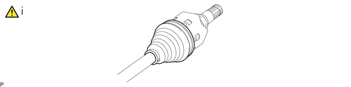
Install the front axle inboard joint boot to the front drive inboard joint assembly.
- NOTICE:
- ·
Keep the grooves free of grease.
·Keep the inside of the front axle inboard joint boot free of foreign matter.
43448F
8.INSTALL FRONT AXLE INBOARD JOINT BOOT CLAMP
|
|
|
| *a | Buckle | - | - |
|
|
Turn |
|
Install in this Direction |
|
|
Place the tip near the center of the lever | - | - |
Install the front axle inboard joint boot clamp to the front axle inboard joint boot and temporarily fold back the lever.
- NOTICE:
- ·
Set the lever into the guide groove correctly.
·Check the band and the lever for any deformation before folding back the lever.
Using water pump pliers, pinch the front axle inboard joint boot clamp to temporarily secure it.
Using a plastic hammer, tap the buckle to secure it while adjusting the clearance between the lever and the groove to make the clearance between the buckle edge and the lever end even.
- NOTICE:
-
Do not damage the front axle inboard joint boot.
43448G
9.INSTALL FRONT NO. 2 AXLE INBOARD JOINT BOOT CLAMP
|
|
|
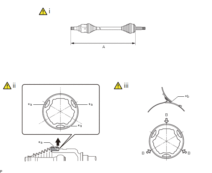
| *a | Indented Portion | *b | Support Point |
Check whether the dimension (A) of each drive shaft is within specification.
- Dimension (A):
for LH Side 587.2 to 595.2 mm (1.93 to 1.95 ft.) for RH Side 891.2 to 899.2 mm (2.92 to 2.95 ft.)
While holding dimension (A) to the specified length, pull the indented portion of the inboard joint grommet outward with your finger, etc. to release air from inside the inboard joint and equalize the air pressure with the atmospheric pressure.
Set the folding support point of the clamp so that it is aligned with any of the A portions indicated by arrows in the illustration.
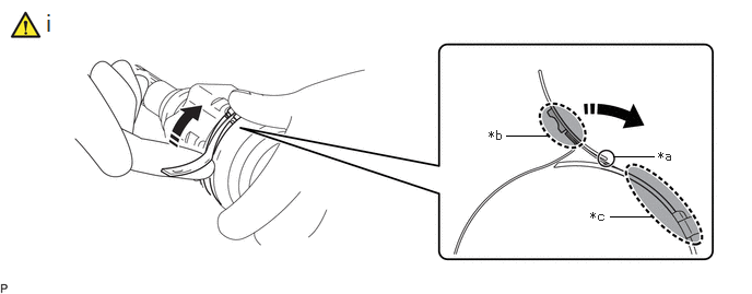
| *a | Fulcrum Point | *b | Lever Push Position |
| *c | Band Support Position | - | - |
Temporarily fold back the lever at the fulcrum point.
- NOTICE:
- ·
Check the band and the lever for any deformation before folding back the lever.
·The lever folds easily at the fulcrum point when pushed at the position shown in the illustration.
·When folding back the lever, do not push at the end of the lever.
6.771,1.49 6.125,1.49 true 5.948,1.417 6.26,1.573 0.313,0.156 10 false *a*a Temporary Claw - -
·If the lever bends in the middle, it may not engage with the temporary claws or may not be held in the correct position.
| *a | Temporary Claw | *b | Fulcrum Point |
|
|
Press down |
|
Contact Point |
|
|
Turn |
|
Install in this Direction |
As shown in the illustration, while pressing the outboard joint area against the work surface, firmly press the lever into place by rolling the outboard joint area forward from the folded fulcrum point to the temporary claw area until a click sound is heard.
- NOTICE:
- ·
Do not damage the deflector.
·Make sure that the outboard joint is in direct contact with the work surface.
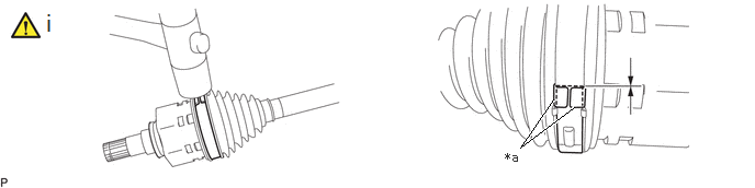
| *a | Buckle | - | - |
Using a plastic hammer, tap the buckle to secure it while adjusting the clearance between the lever and the groove to make the clearance between the buckle edge and the lever end even.
- NOTICE:
- ·
Do not use excessive force when tapping with the plastic hammer.
·Do not damage the front axle outboard joint boot.
43420
10.INSPECT FRONT DRIVE SHAFT ASSEMBLY