BRAKE CONTROL / DYNAMIC CONTROL SYSTEMS ELECTRONICALLY CONTROLLED BRAKE SYSTEM(for HEV Model) C13BA1C Electronic Brake Booster Motor "A" Current Sensor Circuit Voltage Out of Range
DESCRIPTION
When the motor current sensor inside the electric brake booster (brake booster with master cylinder assembly) meets the detection conditions, this DTC is stored.
| DTC No. | Detection Item | DTC Detection Condition | Trouble Area | MIL | DTC Output from | Note |
|---|---|---|---|---|---|---|
| C13BA1C | Electronic Brake Booster Motor "A" Current Sensor Circuit Voltage Out of Range | Motor current sensor current abnormality is detected for 0.2 seconds or more. | Electric brake booster (brake booster with master cylinder assembly) | Comes on | Brake Booster | ·
SAE Code: C13BB (Case 1 to 4) ·
Output ECU: Electric brake booster (brake booster with master cylinder assembly) |
CONFIRMATION DRIVING PATTERN
- NOTICE:
-
When performing the normal judgment procedure, make sure that the driver door is closed and is not opened at any time during the procedure.
- HINT:
- ·
After repair has been completed, clear the DTC and then check that the vehicle has returned to normal by performing the following All Readiness check procedure.
·When clearing the permanent DTCs, refer to the "CLEAR PERMANENT DTC" procedure.
Connect the GTS to the DLC3.
Turn the ignition switch to ON and turn the GTS on.
Clear the DTCs (even if no DTCs are stored, perform the clear DTC procedure).
Turn the ignition switch off.
Turn the ignition switch to ON (READY) and turn the GTS on.
Wait for 1 second or more. [*]
- HINT:
-
[*]: Normal judgment procedure.
-
The normal judgment procedure is used to complete DTC judgment and also used when clearing permanent DTCs.
Enter the following menus: Chassis / Brake Booster / Utility / All Readiness.
Check the DTC judgment result.
- HINT:
- ·
If the judgment result shows NORMAL, the system is normal.
·If the judgment result shows ABNORMAL, the system has a malfunction.
·If the judgment result shows INCOMPLETE, perform driving pattern again.
WIRING DIAGRAM
CAUTION / NOTICE / HINT
- NOTICE:
-
Inspect the fuses for circuits related to this system before performing the following procedure.
PROCEDURE
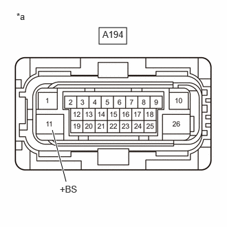
| *a | Front view of wire harness connector
(to Electric Brake Booster (Brake Booster with Master Cylinder Assembly)) |
Make sure that there is no looseness at the locking part and the connecting part of the connectors.
- OK:
The connector is securely connected.
Disconnect the A194 electric brake booster (brake booster with master cylinder assembly) connector.
Check both the connector case and the terminals for deformation and corrosion.
- OK:
No deformation or corrosion.
Measure the voltage according to the value(s) in the table below.
- Standard Voltage:
Tester Connection Condition Specified Condition A194-11 (+BS) - Body ground Always 11 to 14 V
- Result:
Proceed to OK NG
OK
NG