☰ Toyota Frontlander☰ فهرستBrake › BRAKE CONTROL / DYNAMIC CONTROL SYSTEMS › ELECTRONICALLY CONTROLLED BRAKE SYSTEM(for HEV Model)
RM38T0EC
_54
Brake
_112606
BRAKE CONTROL / DYNAMIC CONTROL SYSTEMS
_0608077
ELECTRONICALLY CONTROLLED BRAKE SYSTEM(for HEV Model)
U
BRAKE CONTROL / DYNAMIC CONTROL SYSTEMS ELECTRONICALLY CONTROLLED BRAKE SYSTEM(for HEV Model) TERMINALS OF ECU
CHECK BRAKE BOOSTER WITH MASTER CYLINDER ASSEMBLY
a.
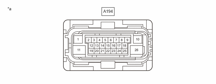
Disconnect the A194 electric brake booster (brake booster with master cylinder assembly) connector and measure the voltage or resistance on the wire harness side.
3.375,0.25 3.792,0.521
0.417,0.271
0.25,0.208 0.563,0.406
0.313,0.198
10
false
*a
3.427,0.292 3.854,0.51
0.427,0.219
10
false
A194
| *a | Front view of wire harness connector
(to Electric Brake Booster (Brake Booster with Master Cylinder Assembly)) |
- | - |
- HINT:
-
The voltage cannot be measured with the connector connected to the electric brake booster (brake booster with master cylinder assembly) as the connector is watertight.
- Standard:
Terminal No. (Symbol) Terminal Description Condition Specified Condition *: Differs depending on the vehicle model
A194-1 (CBKP) Brake control power supply assembly power supply input - - A194-2 (CA1H) CAN communication line 1 (H) - - A194-3 - - - A194-4 (IGR) - Body ground IGR power source input Ignition switch ON 11 to 14 V A194-5 (STP) - Body ground Stop light switch assembly input Stop light switch assembly on → off (Brake pedal depressed → released) 11 to 14 V → Below 1.5 V A194-6 (SKS1) Relative displacement sensor (brake booster with master cylinder assembly) 1 signal input - - A194-7 (SKS2) Relative displacement sensor (brake booster with master cylinder assembly) 2 signal input - - A194-8 (CWKP) - Body ground Brake control power supply assembly signal output Always 11 to 14 V A194-9 (CA2H) CAN communication line 2 (H) - - A194-10 - - - A194-11 (+BS) - Body ground Electric brake booster (Brake booster with master cylinder assembly) power supply input Always 11 to 14 V A194-12 (CA1L) CAN communication line 1 (L) - - A194-13 - - - A194-14 - - - A194-15 - - - A194-16 - - - A194-17 (CTY) - Body ground Front door courtesy light switch assembly input (for driver side) Driver door closed → open 11 to 14 V or pulse output (maximum 14 V)* → Below 1 V A194-18 (CA2L) CAN communication line 2 (L) - - A194-19 (VSK) Relative displacement sensor (brake booster with master cylinder assembly) power supply output - - A194-20 - - - A194-21 (CLIN) - Body ground Brake control power supply assembly signal input - - A194-22 - - - A194-23 - - - A194-24 - - - A194-25 (SKG) Relative displacement sensor (brake booster with master cylinder assembly) ground - - A194-26 (GND) - Body ground Electric brake booster (Brake booster with master cylinder assembly) ground 1 minute or more after disconnecting the cable from the negative (-) auxiliary battery terminal Below 1 Ω
CHECK BRAKE ACTUATOR ASSEMBLY
a.
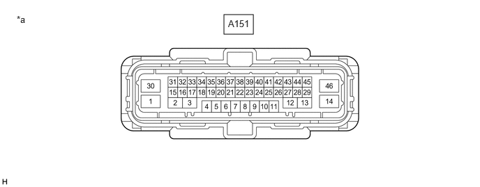
Disconnect the A151 skid control ECU (brake actuator assembly) connector and measure the voltage or resistance on the wire harness side.
3.344,0.219 3.781,0.51
0.438,0.292
0.25,0.208 0.563,0.406
0.313,0.198
10
false
*a
3.406,0.271 3.865,0.479
0.458,0.208
10
false
A151
| *a | Front view of wire harness connector
(to skid control ECU (Brake Actuator Assembly)) |
- | - |
- HINT:
-
The voltage cannot be measured with the connector connected to the skid control ECU (brake actuator assembly) as the connector is watertight.
| Terminal No. (Symbol) | Terminal Description | Condition | Specified Condition |
|---|---|---|---|
| A151-1 (+BM) - Body ground | ABS motor relay power supply input | Always | 11 to 14 V |
| A151-2 | - | - | - |
| A151-3 | - | - | - |
| A151-4 (LBL) - Body ground | Brake fluid level warning switch (Brake master cylinder reservoir assembly) input | - | - |
| A151-5 (CANH) | CAN communication line 1 (H) | - | - |
| A151-6 (SKS1) | Brake pedal stroke sensor 1 signal input | - | - |
| A151-7 (FL-) | Front speed sensor LH (-) signal input | - | - |
| A151-8 | - | - | - |
| A151-9 | - | - | - |
| A151-10 | - | - | - |
| A151-11 (CA2H) | CAN communication line 2 (H) | - | - |
| A151-12 | - | - | - |
| A151-13 | - | - | - |
| A151-14 (GND2) - Body ground | Skid control ECU (brake actuator assembly) ground 2 | 1 minute or more after disconnecting the cable from the negative (-) auxiliary battery terminal | Below 1 Ω |
| A151-15 | - | - | - |
| A151-16 | - | - | - |
| A151-17 (VSK) | Brake pedal stroke sensor assembly power supply output | - | - |
| A151-18 | - | - | - |
| A151-19 (CANL) | CAN communication line 1 (L) | - | - |
| A151-20 | - | - | - |
| A151-21 (FR+) | Front wheel speed RH (+) power supply output | - | - |
| A151-22 (RR+) | Rear wheel speed RH (+) power supply output | - | - |
| A151-23 (RL-) | Rear wheel speed LH (-) signal input | - | - |
| A151-24 (FL+) | Front wheel speed LH (+) power supply output | - | - |
| A151-25 (CA2L) | CAN communication line 2 (L) | - | - |
| A151-26 (FR-) | Front wheel speed RH (-) signal input | - | - |
| A151-27 (STPO) - Body ground | Stop light control relay (stop light switch assembly) output | Always | 11 to 14 V |
| A151-28 | - | - | - |
| A151-29 (SKG) | Brake pedal stroke sensor assembly ground | - | - |
| A151-30 (+BS) - Body ground | ABS solenoid relay power supply | Always | 11 to 14 V |
| A151-31 | - | - | - |
| A151-32 | - | - | - |
| A151-33 (SP1) | Speed sensor signal output for meter | - | - |
| A151-34 | - | - | - |
| A151-35 (PKB) - Body ground | Parking brake status output | - | - |
| A151-36 (IGR) - Body ground | IGR power source input | Ignition switch ON | 11 to 14 V |
| A151-37 (RR-) | Rear speed sensor RH (-) signal input | - | - |
| A151-38 (CSW) - Body ground | VSC OFF switch input | VSC OFF switch is pushed → released | Below 50 Ω → 10 kΩ or higher |
| A151-39 (RL+) | Rear speed sensor LH (+) power supply output | - | - |
| A151-40 | - | - | - |
| A151-41 (STP) - Body ground | Stop light switch assembly signal input | Stop light switch assembly on → off (Brake pedal depressed → released) | 11 to 14 V → Below 1.5 V |
| A151-42 (SKS2) | Brake pedal stroke sensor 2 signal input | - | - |
| A151-43 (STP2) - Body ground | Stop light signal input | Stop light switch assembly on → off (Brake pedal depressed → released) | 11 to 14 V → Below 1.5 V |
| A151-44 (HZRI) - Body ground | Brake hold switch (electric parking brake switch assembly) input | Brake hold switch (electric parking brake switch assembly) on → off (Pressed → not pressed) | Below 1 Ω → 10 kΩ or higher |
| A151-45 (LBL) | Brake fluid level warning switch (Brake master cylinder reservoir assembly) input | - | - |
| A151-46 (GND1) - Body ground | Skid control ECU (brake actuator assembly) ground 1 | 1 minute or more after disconnecting the cable from the negative (-) auxiliary battery terminal | Below 1 Ω |