BRAKE CONTROL / DYNAMIC CONTROL SYSTEMS ELECTRONICALLY CONTROLLED BRAKE SYSTEM(for HEV Model) PRECAUTION
PRECAUTION FOR DISCONNECTING CABLE FROM NEGATIVE AUXILIARY BATTERY TERMINAL
- NOTICE:
-
After the ignition switch is turned off, there may be a waiting time before disconnecting the negative (-) auxiliary battery terminal.
- HINT:
-
When disconnecting and reconnecting the auxiliary battery, there is an automatic learning function that completes learning when the respective system is used.
TROUBLESHOOTING PRECAUTION
When there is a malfunction with terminal contact points or part installation problems, removal and installation of the suspected problem parts may return the system to the normal condition either completely or temporarily.
Before disconnecting a connector or removing and installing a component in order to narrow down the malfunctioning part, make sure to perform the following procedure.
Check for and record any DTCs and Freeze Frame Data that were stored around the time that the malfunction occurred.
If any open circuit DTCs related to intermittent (momentary interruptions) malfunctions are output, check the intermittent monitor.
- NOTICE:
-
When disconnecting a connector or removing a fuse or relay, make sure that the ignition switch is off, the brake pedal is not depressed, and the driver door has been closed for 4 minutes or more*.
-
*: Differs according to vehicle conditions
Since the system may be influenced by malfunctions in systems other than the electronically controlled brake system, be sure to check for DTCs in other systems.
HANDLING PRECAUTION
Do not remove or install electronically controlled brake system parts such as the steering sensor, yaw rate and acceleration sensor (airbag ECU assembly) or brake pedal stroke sensor assembly except when required, as they need to be adjusted correctly after removal and installation.
Be sure to perform preparation before work and confirmation after work is completed by following the directions in the Repair Manual when working on the electronically controlled brake system.
When removing/installing or replacing an electronically controlled brake system related component, disconnect the cable from the negative (-) auxiliary battery terminal before performing the procedure.
- NOTICE:
-
After turning the ignition switch off, waiting time may be required before disconnecting the cable from the negative (-) auxiliary battery terminal. Therefore, make sure to read the disconnecting the cable from the negative (-) auxiliary battery terminal notice before proceeding with work.
This system includes two ECUs, the electric brake booster (brake booster with master cylinder assembly) and the skid control ECU (brake actuator assembly). For this reason, it is necessary to follow the instructions in this manual in order to read the DTCs, freeze frame data, Data List, etc.
- NOTICE:
-
GTS menu items are displayed as follows.
- ·
Electric brake booster (brake booster with master cylinder assembly): Chassis / Brake Booster
·Skid control ECU (brake actuator assembly): Chassis / Brake/EPB*
*: Electric Parking Brake System
If the electric brake booster (brake booster with master cylinder assembly), skid control ECU (brake actuator assembly) or a sensor has been removed and installed, it is necessary to check the system for problems after the parts have been reassembled. Check for DTCs using the GTS. Also check that the system functions and signals received by the ECU are normal using Dealer Mode (Signal Check).
- HINT:
-
If a Dealer Mode (Signal Check) inspection is not performed, a sensor not calibrated malfunction DTC may be stored even if the electric brake booster (brake booster with master cylinder assembly), skid control ECU (brake actuator assembly) and all sensors are normal.
DTC PRECAUTION
Warnings for some DTCs cannot be cleared by only repairing the malfunctioning parts. If the warning is displayed even after repair work, the DTC should be cleared after turning the ignition switch off.
- NOTICE:
-
If a DTC for a malfunctioning part reappears after it is cleared, then it has been stored again.
PRECAUTIONS FOR REMOVAL, INSTALLATION AND REPLACEMENT OF COMPONENTS
After replacing certain components, it may be necessary to update the ECU security key.
Perform "Calibration" after removal, installation or replacement of any of the following components:
Electric brake booster (brake booster with master cylinder assembly)
Skid control ECU (brake actuator assembly)
Brake pedal stroke sensor assembly (including when performing an adjustment)
Brake pedal
Yaw rate and acceleration sensor (airbag ECU assembly)
Perform Dealer Mode (Signal Check) inspection after removal, installation or replacement of any of the following components:
Speed sensor
Speed sensor rotor
CHASSIS DYNAMOMETER PRECAUTION
Enter Inspection Mode to disable TRC and VSC operation when using a chassis dynamometer.
Refer to Inspection Mode Procedure: Click hereGeneral>INTRODUCTION>REPAIR INSTRUCTION>INSPECTION MODE PROCEDURE202201,999999,_V1,_107171,_0486700,RM100000001XIMR,
- CAUTION:
- ·
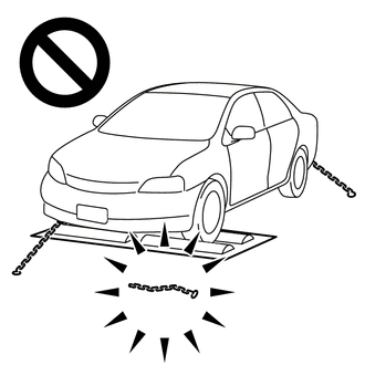
Do not use the drum tester with any of the lock chains disconnected.
·Using the drum tester with a lock chain disconnected could cause the vehicle to begin moving unexpectedly.
·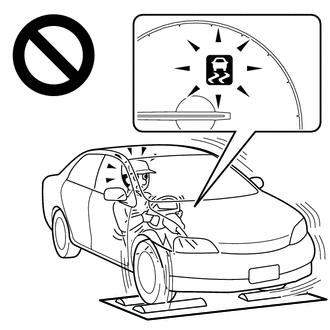
Do not use the drum tester while the TRC or VSC is able to operate.
·TRC or VSC operation could cause the vehicle to begin moving unexpectedly.
CAN COMMUNICATION SYSTEM PRECAUTION
The CAN communication system is used for communication between the electric brake booster (brake booster with master cylinder assembly), skid control ECU (brake actuator assembly), steering sensor, yaw rate and acceleration sensor (airbag ECU assembly) and other ECUs. If there is a malfunction in a CAN communication line, corresponding DTCs for the communication line are output.
If any CAN communication DTCs are output, repair the malfunction, then troubleshoot the electronically controlled brake system while communication is normal.
In order to enable CAN communication, a specific type of wiring is used for the CAN communication lines. The wiring used for each communication line is a twisted pair of wires that have an equal length. A bypass wire should not be used because the data being transmitted will be corrupted.