M20F-FXS, M20G-FXS INTAKE / EXHAUST EXHAUST MANIFOLD INSTALLATION
CAUTION / NOTICE / HINT
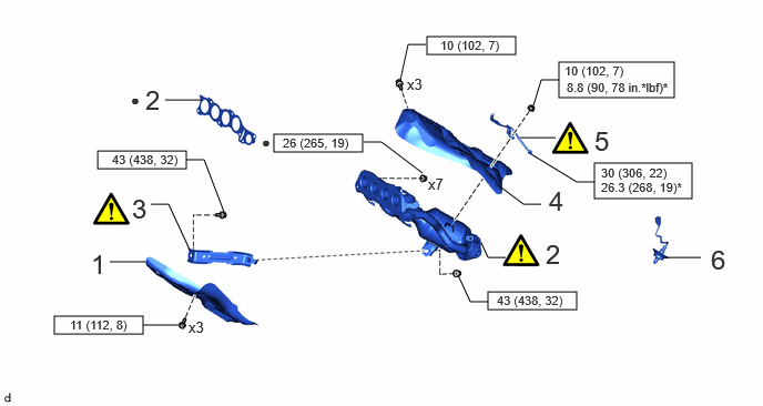
| Procedure | Part Name Code | 
|

|

|
|
|---|---|---|---|---|---|
| 1 | NO. 2 EXHAUST MANIFOLD HEAT INSULATOR | 17168 | - | - | - |
| 2 | EXHAUST MANIFOLD (TWC: Front Catalyst) | 17141 | ( 202307,999999,_51,_144997,_0604323,RM100000002C1OO_01_0099,) 202307,999999,_51,_144997,_0604323,RM100000002C1OO_01_0099,)
|
- | - |
| 3 | MANIFOLD STAY | 17118 | (202307,999999,_51,_144997,_0604323,RM100000002C1OO_01_0192,)
|
- | - |
| 4 | NO. 1 EXHAUST MANIFOLD HEAT INSULATOR | 17167 | - | - | - |
| 5 | NO. 1 VACUUM PIPE | - | (202307,999999,_51,_144997,_0604323,RM100000002C1OO_01_0213,)
|
- | - |
| 6 | AIR FUEL RATIO SENSOR | 89467B | - | - | - |

|
N*m (kgf*cm, ft.*lbf): Specified torque | * | For use with a union nut wrench |
| ● | Non-reusable part | - | - |
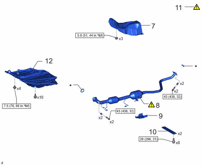
| Procedure | Part Name Code |
|
|
|
|
|---|---|---|---|---|---|
| 7 | FRONT NO. 1 FLOOR HEAT INSULATOR | 58151 | - | - | - |
| 8 | FRONT EXHAUST PIPE ASSEMBLY (TWC: Rear Catalyst) | 17410 | (202307,999999,_51,_144997,_0604323,RM100000002C1OO_01_0211,)
|
- | - |
| 9 | COVER | - | - | - | - |
| 10 | FRONT FLOOR CENTER BRACE | 57533B | - | - | - |
| 11 | INSPECT FOR EXHAUST GAS LEAK | - | (202307,999999,_51,_144997,_0604323,RM100000002C1OO_01_0208,)
|
- | - |
| 12 | NO. 1 ENGINE UNDER COVER ASSEMBLY | 51410 | - | - | - |
|
|
N*m (kgf*cm, ft.*lbf): Specified torque | ● | Non-reusable part |
PROCEDURE

 17168
1.INSTALL NO. 2 EXHAUST MANIFOLD HEAT INSULATOR
17168
1.INSTALL NO. 2 EXHAUST MANIFOLD HEAT INSULATOR
- Torque:
- 11 N*m (112 kgf*cm, 8 ft.*lbf)
17141
2.INSTALL EXHAUST MANIFOLD (TWC: Front Catalyst)
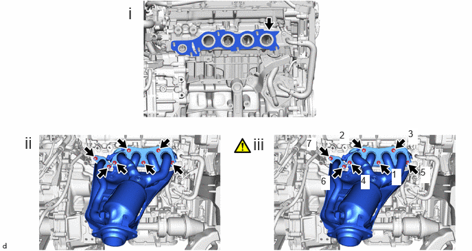
Install a new exhaust manifold to head gasket to the cylinder head sub-assembly.
Using a 12 mm deep socket wrench, temporarily install the exhaust manifold (TWC: Front Catalyst) to the cylinder head sub-assembly with 7 new nuts.
Using the 12 mm deep socket wrench, tighten the 7 nuts in the order shown in the illustration.
- Torque:
- 26 N*m (265 kgf*cm, 19 ft.*lbf)
17118
3.INSTALL MANIFOLD STAY
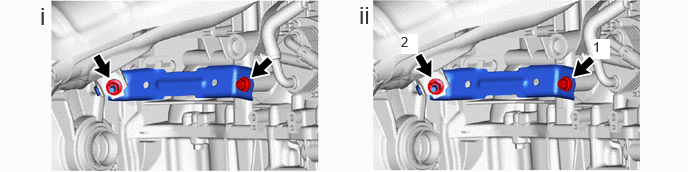
Temporarily install the manifold stay to the exhaust manifold (TWC: Front Catalyst) and cylinder block sub-assembly with the bolt and nut.
Tighten the bolt and nut in the order shown in the illustration.
- Torque:
- 43 N*m (438 kgf*cm, 32 ft.*lbf)
17167
4.INSTALL NO. 1 EXHAUST MANIFOLD HEAT INSULATOR
- Torque:
- 10 N*m (102 kgf*cm, 7 ft.*lbf)
5.INSTALL NO. 1 VACUUM PIPE
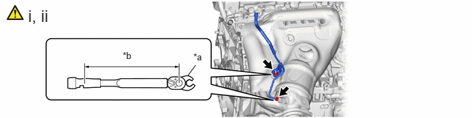
| *a | Union Nut Wrench | *b | Torque Wrench Fulcrum Length |
Using a 14 mm union nut wrench, connect the No. 1 vacuum pipe to the exhaust manifold (TWC: Front Catalyst).
- Torque:
- 30 N*m (306 kgf*cm, 22 ft.*lbf)
- HINT:
- ·
Using a 14 mm union nut wrench, connect the No. 1 vacuum pipe to the exhaust manifold (TWC: Front Catalyst).
·When using a 14 mm union nut wrench (fulcrum length of 25 mm (0.866 in.)) + torque wrench (fulcrum length of 180 mm (6.38 in.)): 26.3 N*m (268 kgf*cm, 19 ft.*lbf)
Install the No. 1 vacuum pipe to the exhaust manifold (TWC: Front Catalyst) with the nut.
- Torque:
- 10 N*m (102 kgf*cm, 7 ft.*lbf)
- HINT:
-
When using a 10 mm union nut wrench (fulcrum length of 22 mm (0.866 in.)) + torque wrench (fulcrum length of 155 mm (6.1 in.)): 8.8 N*m (90 kgf*cm, 78 in.*lbf)
89467B
6.INSTALL AIR FUEL RATIO SENSOR
58151
7.INSTALL FRONT NO. 1 FLOOR HEAT INSULATOR
17410
8.INSTALL FRONT EXHAUST PIPE ASSEMBLY (TWC: Rear Catalyst)
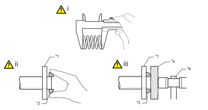
| *1 | Exhaust Manifold (TWC: Front Catalyst) or Front Exhaust Pipe Assembly (TWC: Rear Catalyst) | *2 | Gasket |
| *a | Wooden Block | *b | Plastic Hammer |
Using a vernier caliper, measure the free length of the compression springs.
| Standard Length (Front) | 43 mm (1.69 in.) |
| Standard Length (Rear) | 40 mm (1.57 in.) |
| Minimum Free Length (Front) | 41.5 mm (1.63 in.) |
| Minimum Free Length (Rear) | 38.5 mm (1.52 in.) |
If the free length is less than the minimum, replace the compression spring.
temporarily install 2 new gaskets to the exhaust manifold (TWC: Front Catalyst) and front exhaust pipe assembly (TWC: Rear Catalyst).
Using a plastic hammer and wooden block, tap in each gasket until its surface is flush with the exhaust manifold (TWC: Front Catalyst) and front exhaust pipe assembly (TWC: Rear Catalyst).
- NOTICE:
- ·
Be sure to install the gasket in the correct direction.
·Do not reuse the gaskets.
·Do not damage the gaskets.
·Do not push in the gaskets by using the exhaust pipes when connecting them.
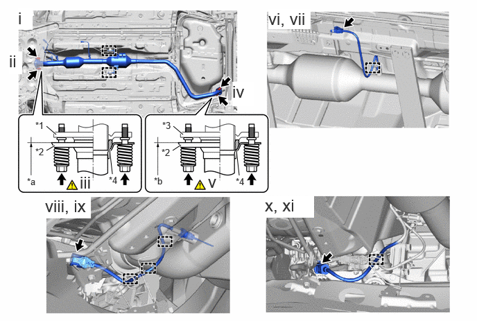
| *1 | Exhaust Manifold (TWC: Front Catalyst) | *2 | Front Exhaust Pipe Assembly (TWC: Rear Catalyst) |
| *3 | Tail Exhaust Pipe Assembly | *4 | Gasket |
| *a | Space between Flanges: 8.5 mm (0.335in.) | *b | Space between Flanges: 6.5 mm (0.256in.) |
Connect the front exhaust pipe assembly to the 2 exhaust pipe supports.
Install the front exhaust pipe assembly (TWC: Rear Catalyst) to the exhaust manifold (TWC: Front Catalyst) with the 2 compression springs and 2 bolts.
- Torque:
- 43 N*m (438 kgf*cm, 32 ft.*lbf)
After installation, check that the space between the flanges of the exhaust manifold (TWC: Front Catalyst) and front exhaust pipe assembly (TWC: Rear Catalyst) is consistent front-to-rear and left-to-right.
Install the front exhaust pipe assembly (TWC: Rear Catalyst) to the tail exhaust pipe assembly with the 2 compression springs and 2 bolts.
- Torque:
- 43 N*m (438 kgf*cm, 32 ft.*lbf)
After installation, check that the space between the flanges of the front exhaust pipe assembly (TWC: Rear Catalyst) and tail exhaust pipe assembly is consistent front-to-rear and left-to-right.
Engage the wire harness clamp.
Connect the heated oxygen sensor connector.
Engage the 3 wire harness clamps.
Connect the exhaust gas temperature sensor connector.
Engage the wire harness clamp.
Connect the exhaust gas temperature sensor connector.
9.INSTALL COVER
57533B
10.INSTALL FRONT FLOOR CENTER BRACE
- Torque:
- 29 N*m (296 kgf*cm, 21 ft.*lbf)
11.INSPECT FOR EXHAUST GAS LEAK
51410
12.INSTALL NO. 1 ENGINE UNDER COVER ASSEMBLY