M20F-FXS, M20G-FXS BATTERY / CHARGING CHARGING SYSTEM Auxiliary Battery is Discharged
DESCRIPTION
General causes of auxiliary battery depletion include the switches of electrical devices mistakenly left on, service life of the auxiliary battery, charging device malfunction, or application of excessive electrical load by the customer, etc.
Therefore, it is important to properly grasp the usage conditions of the customer's vehicle and carry out appropriate troubleshooting (systematized failure diagnosis).
- HINT:
-
If the power is mistakenly left on, the operation history may remain in the certification ECU (smart key ECU assembly).
PROCEDURE
Carry out customer problem analysis with the customer, and check the vehicle condition and usage conditions at the time of auxiliary battery depletion.
- Result:
Proceed to NEXT
NEXT
- HINT:
-
If the result of the auxiliary battery inspection is NG, charge or replace the auxiliary battery according to the inspection result, and proceed to the next step.
- Result:
Proceed to NEXT
NEXT
Perform the Health Check using the GTS.
Check the DTCs.
- Result:
Result Proceed to DTCs are not output A DTCs are output B
A
B
- HINT:
-
Some of the control history can be checked from "Vehicle Control History (RoB)".
Record the output control history.
- Powertrain > Hybrid Control > Utility
-
Tester Display Vehicle Control History (RoB) - 50005 397 55
- Result:
Proceed to NEXT
NEXT
Check that "Auxiliary Battery Discharge at IG OFF" is not output in Vehicle Control History (RoB).
- HINT:
-
A history is stored when the following conditions are met at the same time.
- ·
Ignition switch off and average current of auxiliary battery 60 mA or higher
·Ignition switch off continuously for 8 hours or more
- Result:
Result Proceed to "Auxiliary Battery Discharge at IG OFF" is not output A "Auxiliary Battery Discharge at IG OFF" is output B
A
B
Turn all switches off and turn the ignition switch off.
Wait for 30 minutes or more with the door lock locked.
- HINT:
- ·
Once the door lock is locked, keep the electrical key transmitter sub-assembly (electrical key) 3 m (9.84 ft.) or more away from the vehicle.
·Because the system will not sleep while any door and/or the hood is open, take steps such as securing the courtesy switch to make the system recognize the doors and hood as closed when carrying out the operation.
·If the vehicle is equipped with a power back door, the system will not sleep if the back door is not closed. Ensure that the back door is closed before carrying out the operation.
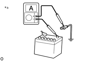
| *a | The illustration is for reference only |
Check the dark current.
- Result:
Result Proceed to 120 mA or less A Higher than 120 mA B
- HINT:
- ·
Close the doors and hood or make the system recognize the doors and hood as closed when checking the dark current.
·Do not bring the electrical key transmitter sub-assembly (electrical key) near the vehicle or operate any switches when checking the dark current, as doing so will cause the system to start and increase the current.
·Connect the electrical tester in series when checking the dark current to prevent the auxiliary battery negative (-) circuit from being disconnected.
If the negative (-) circuit is disconnected, leave the unit for 30 minutes or more with the electrical tester connected between the negative (-) terminal of the auxiliary battery and the terminal in series, and check the dark current once the current is stable.
·If the vehicle is equipped with a kick sensor and your foot, etc. is detected by the sensor, the current value may increase momentarily and make it impossible to properly measure the current.
A
B
Check that "Auxiliary Battery Discharge at Running" is not output in Vehicle Control History (RoB).
- HINT:
-
A history is stored if one of the following conditions is met.
- ·
Auxiliary battery voltage while driving is 11 V or less continuously for 20 seconds or more
·Total charge/discharge while driving is 4.5 Ah or more
- Result:
Result Proceed to "Auxiliary Battery Discharge at Running" is not output A "Auxiliary Battery Discharge at Running" is output B
A
B
Check that "Auxiliary Battery Voltage Low at IG OFF" is not output in Vehicle Control History (RoB).
- HINT:
-
A history is stored when the ignition switch is off and the auxiliary battery voltage is 11.5 V or less continuously for 10 minutes or more.
- Result:
Result Proceed to "Auxiliary Battery Voltage Low at IG OFF" is not output A "Auxiliary Battery Voltage Low at IG OFF" is output B
A
B
Based on the result of customer problem analysis, check the factors that may lead to auxiliary battery depletion.
- Result:
Result Proceed to No problems A Illumination, such as cabin and luggage illumination, is mistakenly left on B Ignition switch is left to ACC or ON (ignition switch is mistakenly left on) C Optional electrical components are mistakenly left on D The storage location of the electrical key is within 1 m (3.28 ft.) from the vehicle E When the customer drives for 30 minutes or less a week F
- HINT:
- ·
If the storage location of the electrical key transmitter sub-assembly (electrical key) is within approximately 1 m (3.28 ft.) of the vehicle, the system may become unable to sleep, leading to auxiliary battery depletion due to repeated detection and non-detection by the vehicle exterior detection function of the key.
If this applies, have the customer change the storage location of the electrical key transmitter sub-assembly (electrical key) to an area that is separated from the vehicle by at least 2 m (6.56 ft.).
·If the power is mistakenly left on, the operation history may remain in the certification ECU (smart key ECU assembly).
A
B
C
D
E
F
Check that all the switches installed in the vehicle for systems that operate with the ignition switch off operate normally.
- HINT:
Examples of Switches that Function with Ignition Switch Off Switch Operation Door handle switch Hold and pull door handle Door courtesy switch Open/close door Luggage door switch Press switch Pawl switch, half latch switch Jiggle with the door and/or luggage closed (open/close operation) Dimmer switch Headlight flashing, headlight on/off Door lock switch Lock, unlock Slide door open switch Sliding door open/close operation Luggage opener switch Press switch Fuel lid opener switch Opening operation Power seat switch Power seat operation Intrusion sensor OFF switch Intrusion sensor on/off
Operate each switch while checking the dark current, and check that the dark current drops to 120 mA or less after operation.
- NOTICE:
-
The electrical tester may become damaged due to an increase in dark current from switch operation. Therefore, check the dark current with the electrical tester measurement range set at maximum, and drop the measurement range gradually according to the changes in current.
- HINT:
-
After checking that the dark current drops to 120 mA or less, check the next switch.
- Result:
Result Proceed to Malfunction is not reproduced A Malfunction is reproduced B
A
B
Check "Time of Long Term Leaving with IG OFF (1st, 2nd, 3rd)".
- HINT:
-
A history is stored when the ignition switch is off continuously for 60 days.
- Powertrain > Hybrid Control > Data List
-
Tester Display Time of Long Term Leaving with IG OFF (1st) Time of Long Term Leaving with IG OFF (2nd) Time of Long Term Leaving with IG OFF (3rd) - 50003 397 278,279,280
- Result:
Result Proceed to "Time of Long Term Leaving with IG OFF (1st, 2nd, 3rd)" are all 0 days A Any "Time of Long Term Leaving with IG OFF (1st, 2nd, 3rd)" is 60 days or more B
A
B
- Result:
Proceed to OK NG
OK
NG
Check the customer problem analysis chart and vehicle, and check whether there are any optional electrical components.
- Result:
Result Proceed to Optional electrical components are not installed A Optional electrical components are installed B
A
B
- Result:
Result Proceed to Current consumption is below 10 A A Current consumption is 10 A or higher B
A
B
Check the customer problem analysis chart and vehicle, and check whether there are any optional electrical components.
- Result:
Result Proceed to Optional electrical components are not installed A Optional electrical components are installed B
A
B
Remove optional electrical components.
- NOTICE:
-
Check the installation condition of the electrical components carefully before removal.
Check the dark current.
- Result:
Result Proceed to Decreases to 120 mA or less A Remains higher than 120 mA B
- HINT:
- ·
Close the doors and hood or make the system recognize the doors and hood as closed when checking the dark current.
·Do not bring the electrical key transmitter sub-assembly (electrical key) near the vehicle or operate any switches when checking the dark current, as doing so will cause the system to start and increase the current.
·Connect the electrical tester in series when checking the dark current to prevent the auxiliary battery negative (-) circuit from being disconnected.
If the negative (-) circuit is disconnected, leave the unit for 30 minutes or more with the electrical tester connected between the negative (-) terminal of the auxiliary battery and the terminal in series, and check the dark current once the current is stable.
·If the vehicle is equipped with a power back door, the system will not sleep if the back door is not closed. Ensure that the back door is closed before carrying out the operation.
·If the vehicle is equipped with a kick sensor and your foot, etc. is detected by the sensor, the current value may increase momentarily and make it impossible to properly measure the current.
Install the optional electrical components.
A
B
Check all the switches installed in the vehicle for systems that operate with the ignition switch off to determine whether they are stuck ON.
- HINT:
- ·
Check visually, by normal operation and by pushing and/or jiggling the switches.
·The following are examples of switches that function with the ignition switch off.
Examples of Switches that Function with Ignition Switch Off Door handle switch Door courtesy switch Luggage door switch Pawl switch, half latch switch Dimmer switch Door lock switch Slide door open switch Luggage opener switch Fuel lid opener switch Power seat switch Intrusion sensor OFF switch
- Result:
Result Proceed to No switch malfunction A Switch malfunction B
A
B
Narrow down the malfunctioning system by checking the dark current while removing fuses starting from the one closest to the system, actuator or ECU (farthest from the power source).
- HINT:
- ·
From the wiring diagram, select ECUs and components to which voltage is applied constantly via the +B voltage source, and remove those fuses 1 system at a time.
·Fuses must be removed one at a time. Do not remove 2 or more fuses simultaneously.
·Remove the fuses in the order that is most likely to allow the trouble area to be specified, as multiple ECUs or components may be connected to a single fuse.
·Once a single system check is ended, proceed to the next system check without re-attaching the removed fuse(s).
·Remove the fuses in order, and if a system with current of 120 mA or less is found, check the ECUs and/or components of that system.
- Result:
Proceed to NEXT
- HINT:
- ·
Close the doors and hood or make the system recognize the doors and hood as closed when checking the dark current.
·Do not bring the electrical key transmitter sub-assembly (electrical key) near the vehicle or operate any switches when checking the dark current, as doing so will cause the system to start and increase the current.
·Connect the electrical tester in series when checking the dark current to prevent the auxiliary battery negative (-) circuit from being disconnected.
If the negative (-) circuit is disconnected, leave the unit for 30 minutes or more with the electrical tester connected between the negative (-) terminal of the auxiliary battery and the terminal in series, and check the dark current once the current is stable.
·If the vehicle is equipped with a power back door, the system will not sleep if the back door is not closed. Ensure that the back door is closed before carrying out the operation.
·If the vehicle is equipped with a kick sensor and your foot, etc. is detected by the sensor, the current value may increase momentarily and make it impossible to properly measure the current.
NEXT