☰ Toyota Frontlander☰ فهرستEngine / Hybrid System › M20F-FXS, M20G-FXS FUEL › FUEL PRESSURE SENSOR(for High Pressure)
RM38T0EC
_51
Engine / Hybrid System
_144959
M20F-FXS, M20G-FXS FUEL
_0604269
FUEL PRESSURE SENSOR(for High Pressure)
G
M20F-FXS, M20G-FXS FUEL FUEL PRESSURE SENSOR(for High Pressure) INSPECTION
PROCEDURE

 89458
1.INSPECT FUEL PRESSURE SENSOR
89458
1.INSPECT FUEL PRESSURE SENSOR
a.
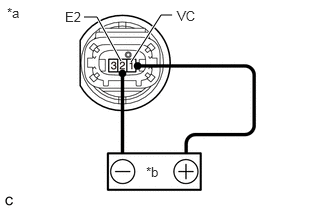
Check the fuel pressure sensor output voltage.
i.
0.875,0.177 1.01,0.177
1.01,0.177 1.26,0.635
true
1.365,0.646 1.677,0.156
1.677,0.156 1.792,0.156
true
0.073,0.052 0.385,0.208
0.313,0.156
10
false
*a
1.521,1.708 1.833,1.865
0.313,0.156
10
false
*b
0.677,0.094 0.99,0.292
0.313,0.198
10
false
E2
1.844,0.083 2.156,0.281
0.313,0.198
10
false
VC
| *a | Component without harness connected
(Fuel Pressure Sensor) |
| *b | Voltage Applied between Terminals |
Apply 5 V between terminals 1 (VC) and 2 (E2).
- NOTICE:
- ·
Be careful when connecting the leads as the fuel pressure sensor may be damaged if the leads are connected to the wrong terminals.
·Do not apply more than 6 V to terminals 1 (VC) or 2 (E2).
- HINT:
-
If a stable power supply is not available, connect 4 nickel-metal hydride batteries (1.2 V each) or equivalent in series.
ii.
1.104,0.396 1.229,0.396
1.229,0.396 1.583,1.094
true
1.677,1.094 1.833,0.396
1.833,0.396 1.969,0.396
true
0.104,0.063 0.417,0.219
0.313,0.156
10
false
*a
0.875,0.323 1.188,0.521
0.313,0.198
10
false
PR
2.021,0.323 2.333,0.521
0.313,0.198
10
false
E2
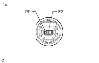
| *a | Component without harness connected
(Fuel Pressure Sensor) |
Measure the voltage according to the value(s) in the table below.
- Standard Voltage:
Tester Connection Condition Specified Condition 3 (PR) - 2 (E2) Pressure not applied to fuel pressure sensor Approximately 0.4 to 0.6 V*
*: The output voltage changes depending on the voltage applied to the terminals.
If the result is not as specified, replace the fuel pressure sensor.