RM38T0EC
_51
Engine / Hybrid System
_144959
M20F-FXS, M20G-FXS FUEL
_0604268
FUEL PRESSURE SENSOR
G
M20F-FXS, M20G-FXS FUEL FUEL PRESSURE SENSOR INSPECTION
PROCEDURE

 89458H
1.INSPECT NO. 2 FUEL PRESSURE SENSOR
89458H
1.INSPECT NO. 2 FUEL PRESSURE SENSOR
a.
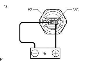
Check the No. 2 fuel pressure sensor output voltage.
i.
1.802,0.771 1.344,0.333
1.344,0.333 1.177,0.333
true
1.99,0.771 2.406,0.333
2.406,0.333 2.573,0.333
true
0.135,0.135 0.448,0.292
0.313,0.156
10
false
*a
1.521,1.844 1.833,2
0.313,0.156
10
false
*b
0.99,0.26 1.302,0.458
0.313,0.198
10
false
E2
2.625,0.271 2.938,0.469
0.313,0.198
10
false
VC
| *a | Component without harness connected
(No. 2 Fuel Pressure Sensor) |
| *b | Voltage Applied between Terminals |
Apply 5 V between terminals 1 (VC) and 3 (E2).
- NOTICE:
- ·
Be careful when connecting the leads, as the No. 2 fuel pressure sensor may be damaged if the leads are connected to the wrong terminals.
·Do not apply more than 6 V to terminals 1 (VC) or 3 (E2).
- HINT:
-
If a stable power supply is not available, connect 4 nickel-metal hydride batteries (1.2 V each) or equivalent in series.
ii.

1.615,1.156 1.313,1.667
1.313,1.667 1.313,1.833
true
1.729,1.167 1.99,1.667
1.99,1.667 1.99,1.833
true
0.125,0.125 0.438,0.281
0.313,0.156
10
false
*a
1.25,1.865 1.563,2.063
0.313,0.198
10
false
E2
1.885,1.865 2.198,2.063
0.313,0.198
10
false
PFL
| *a | Component without harness connected
(No. 2 Fuel Pressure Sensor) |
Measure the voltage according to the value(s) in the table below.
- Standard Voltage:
Tester Connection Condition Specified Condition 2 (PFL) - 3 (E2) Pressure not applied to No. 2 fuel pressure sensor Approximately 0.56 to 0.94 V*
*: The output voltage changes depending on the voltage applied to the terminals.
If the result is not as specified, replace the No. 2 fuel pressure sensor.