M20F-FXS, M20G-FXS ENGINE MECHANICAL CYLINDER BLOCK DISASSEMBLY
CAUTION / NOTICE / HINT
The necessary procedures (adjustment, calibration, initialization or registration) that must be performed after parts are removed and installed, or replaced during cylinder block removal/installation are shown below.
| Replaced Part or Performed Procedure | Necessary Procedure | Effect/Inoperative Function when Necessary Procedure not Performed | Link |
|---|---|---|---|
| Replacement of piston or piston ring | Inspection after repair | ·
Poor idle, etc. ·
Engine start function, etc. |
( 202307,999999,_51,_144956,_0604911,RM100000002BWPD,) 202307,999999,_51,_144956,_0604911,RM100000002BWPD,)
|
CAUTION / NOTICE / HINT
| Procedure | Part Name Code | 
|

|

|
|
|---|---|---|---|---|---|
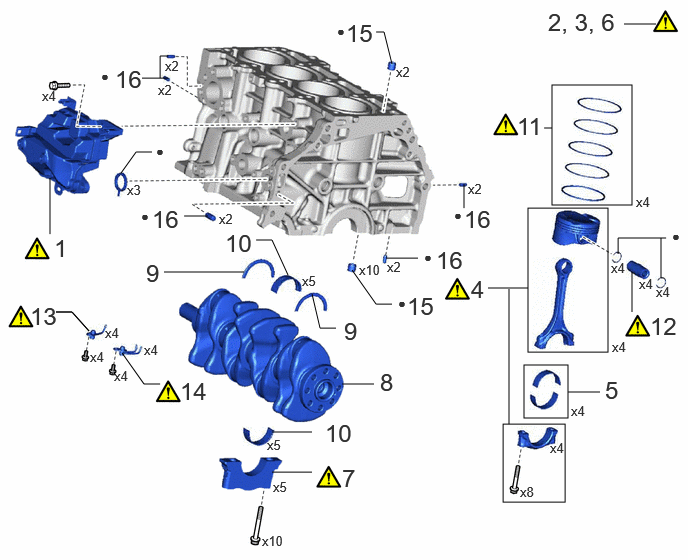
| 1 | NO. 1 VENTILATION CASE | 12211 | - | - | - |
| 2 | INSPECT CONNECTING ROD THRUST CLEARANCE | - | (202307,999999,_51,_144958,_0604256,RM100000002BTSM_01_0160,)
|
- | - |
| 3 | INSPECT CONNECTING ROD OIL CLEARANCE | - | (202307,999999,_51,_144958,_0604256,RM100000002BTSM_01_0161,)
|
- | - |
| 4 | PISTON WITH CONNECTING ROD | - | - | - | - |
| 5 | CONNECTING ROD BEARING | - | - | - | - |
| 6 | INSPECT CRANKSHAFT THRUST CLEARANCE | - | (202307,999999,_51,_144958,_0604256,RM100000002BTSM_01_0158,)
|
- | - |
| 7 | CRANKSHAFT BEARING CAP | - | (202307,999999,_51,_144958,_0604256,RM100000002BTSM_01_0155,)
|
- | - |
| 8 | CRANKSHAFT | 13411 | - | - | - |
| 9 | CRANKSHAFT THRUST WASHER | 11791 | - | - | - |
| 10 | CRANKSHAFT BEARING | - | - | - | - |
| 11 | PISTON RING SET | 13011 | - | - | - |
| 12 | PISTON PIN | 13101A | (202307,999999,_51,_144958,_0604256,RM100000002BTSM_01_0150,)
|
- | - |
| 13 | NO. 1 OIL NOZZLE SUB-ASSEMBLY | 15708 | (202307,999999,_51,_144958,_0604256,RM100000002BTSM_01_0149,)
|
- | - |
| 14 | NO. 2 OIL NOZZLE SUB-ASSEMBLY | 15709 | (202307,999999,_51,_144958,_0604256,RM100000002BTSM_01_0148,)
|
- | - |
| 15 | RING PIN | 11115A | (202307,999999,_51,_144958,_0604256,RM100000002BTSM_01_0163,)
|
- | - |
| 16 | STRAIGHT PIN | 11114A | (202307,999999,_51,_144958,_0604256,RM100000002BTSM_01_0162,)
|
- | - |
| ● | Non-reusable part | - | - |
PROCEDURE

 12211
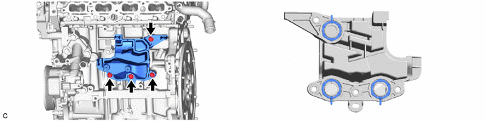
1.REMOVE NO. 1 VENTILATION CASE
12211
1.REMOVE NO. 1 VENTILATION CASE
|
|
|
2.INSPECT CONNECTING ROD THRUST CLEARANCE
Using a dial indicator, measure the thrust clearance while moving the connecting rod sub-assembly back and forth.
- Standard Thrust Clearance:
0.160 to 0.512 mm (0.00630 to 0.0202 in.)
- Maximum Thrust Clearance:
0.512 mm (0.0202 in.)
- HINT:
-
If the thrust clearance is more than the maximum, replace the connecting rod. If necessary, replace the crankshaft.
3.INSPECT CONNECTING ROD OIL CLEARANCE
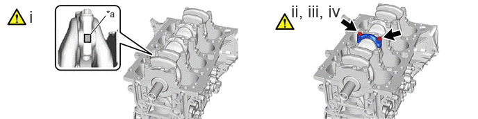
| *a | Alignment Mark | - | - |
Note the alignment marks on the connecting rod and connecting rod cap so that they can be reinstalled to their original locations.
Using an E12 "TORX" socket wrench, remove the 2 connecting rod bolts and connecting rod cap.
Clean the crank pin and connecting rod bearing.
- NOTICE:
-
Check the crank pin and connecting rod bearing for pitting and scratches.
- HINT:
-
If the crank pin or connecting rod bearing is damaged, replace the connecting rod bearings. If necessary, replace the crankshaft.
Check the crank pin and connecting rod bearing for pitting and scratches.
- HINT:
-
If the crank pin or connecting rod bearing is damaged, replace the connecting rod bearings. If necessary, replace the crankshaft.
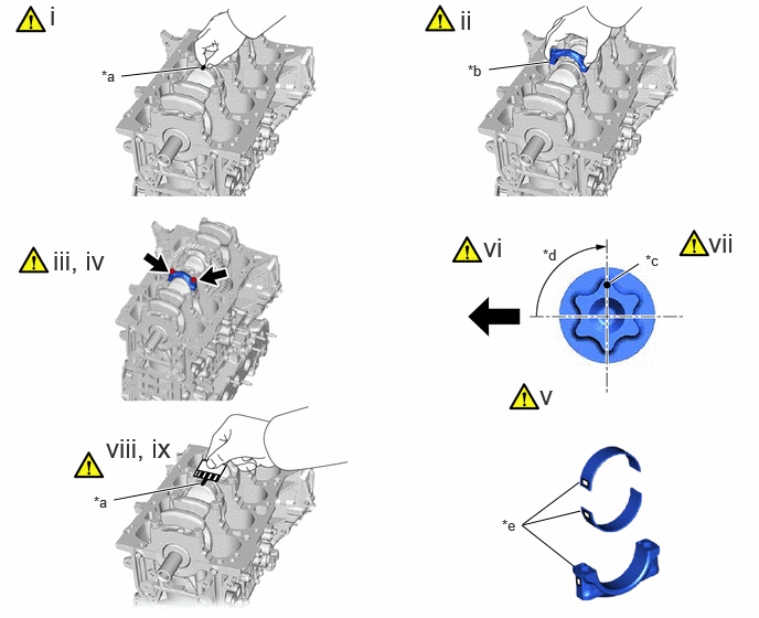
| *a | Plastigage | *b | Front Mark |
| *c | Paint Mark | *d | 90° |
| *e | 1, 2 or 3 Mark | - | - |

|
Front of Engine | - | - |
Lay a strip of Plastigage on the crank pin.
Check that the front mark of the connecting rod cap is facing the correct direction, and install the connecting rod cap to the connecting rod.
Apply a light coat of engine oil to the threads and under the heads of the 2 connecting rod bolts.
Using an E12 "TORX" socket wrench, install and alternately tighten the 2 connecting rod bolts in several steps.
- Torque:
- 38 N*m (387 kgf*cm, 28 ft.*lbf)
Mark the front of each connecting rod bolt with paint.
Tighten the connecting rod bolts 90° as shown in the illustration.
- NOTICE:
-
Do not turn the crankshaft during the measurement.
Remove the 2 connecting rod bolts and connecting rod cap.
- HINT:
-
Keep the connecting rod bearing and connecting rod cap together.
Measure the Plastigage at its widest point.
- Standard Oil Clearance:
0.032 to 0.065 mm (0.00126 to 0.00256 in.)
- Maximum Oil Clearance:
0.065 mm (0.00256 in.)
- HINT:
- ·
If the oil clearance is more than the maximum, replace the connecting rod bearings. If necessary, replace the crankshaft.
·If replacing a connecting rod bearing, select a new one with the same number as marked on the connecting rod cap. There are 3 sizes of standard connecting rod bearings, marked "1", "2" or "3" accordingly.
- Standard Connecting Rod Big End Inside Diameter:
Mark Specified Condition 1 51.000 to 51.008 mm (2.00787 to 2.00818 in.) 2 51.008 to 51.016 mm (2.00818 to 2.00850 in.) 3 51.016 to 51.024 mm (2.00850 to 2.00881 in.)
- Standard Connecting Rod Bearing Center Wall Thickness:
Mark Specified Condition 1 1.483 to 1.487 mm (0.05839 to 0.05854 in.) 2 1.487 to 1.491 mm (0.05854 to 0.05870 in.) 3 1.491 to 1.495 mm (0.05870 to 0.05886 in.)
- Standard Crank Pin Diameter:
47.992 to 48.000 mm (1.88945 to 1.88976 in.)
- NOTICE:
-
Remove the Plastigage completely after the measurement.
Perform the inspection above for each cylinder.
4.REMOVE PISTON WITH CONNECTING ROD
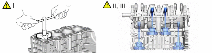
Using a ridge reamer, remove all the carbon from the top of each cylinder.
Remove the 8 connecting rod bolts, 4 connecting rod caps and 4 connecting rod bearings.
Push the 4 pistons, 4 connecting rods and 4 connecting rod bearings out through the top of the cylinder block sub-assembly.
- HINT:
- ·
Keep the connecting rod bearings, connecting rods and connecting rod caps together.
·Arrange the removed parts in such a way that they can be reinstalled to their original locations.
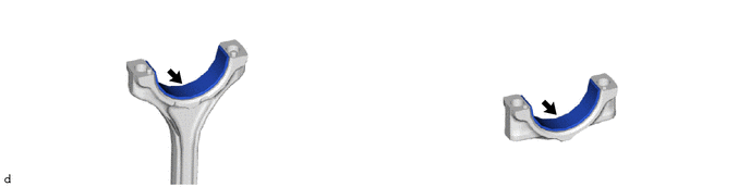
5.REMOVE CONNECTING ROD BEARING
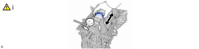
6.INSPECT CRANKSHAFT THRUST CLEARANCE
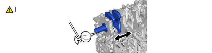
Using a dial indicator, measure the crankshaft thrust clearance while prying the crankshaft back and forth with a screwdriver.
- Standard Thrust Clearance:
0.02 to 0.22 mm (0.000787 to 0.00866 in.)
- Maximum Thrust Clearance:
0.22 mm (0.00866 in.)
- HINT:
-
If the thrust clearance is more than the maximum, replace the crankshaft thrust washers as a set. If necessary, replace the crankshaft.
- Standard Thrust Washer Thickness:
2.415 to 2.470 mm (0.0951 to 0.0972 in.)
- Standard Thrust Washer Thickness:
2.415 to 2.470 mm (0.0951 to 0.0972 in.)
7.REMOVE CRANKSHAFT BEARING CAP
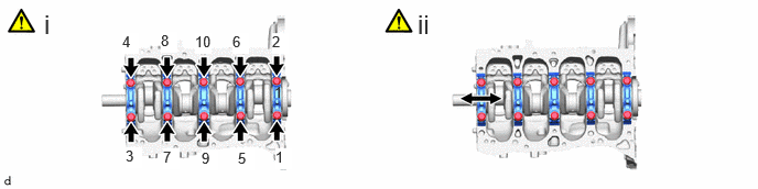
Uniformly loosen and remove the 10 crankshaft bearing cap set bolts in several steps in the order shown in the illustration.
Using the 2 removed crankshaft bearing cap set bolts, remove the 5 crankshaft bearing caps from the cylinder block sub-assembly by wiggling each crankshaft bearing cap back and forth.
13411
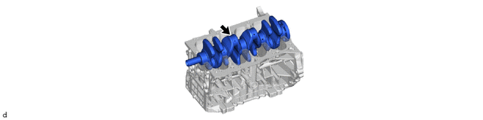
8.REMOVE CRANKSHAFT
11791
9.REMOVE CRANKSHAFT THRUST WASHER
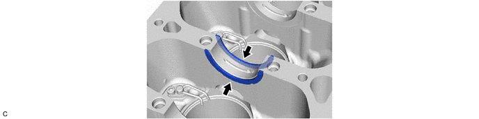
10.REMOVE CRANKSHAFT BEARING
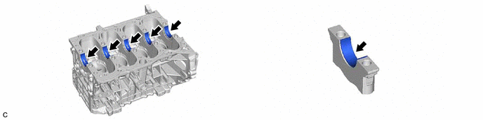
13011
11.REMOVE PISTON RING SET
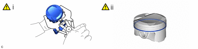
Using a piston ring expander, remove the No. 1 compression ring and No. 2 compression ring from the piston.
Remove the oil ring expander, upper side rail and lower side rail from the piston by hand.
- HINT:
-
Arrange the removed parts in such a way that they can be reinstalled to their original locations.
13101A
12.REMOVE PISTON PIN
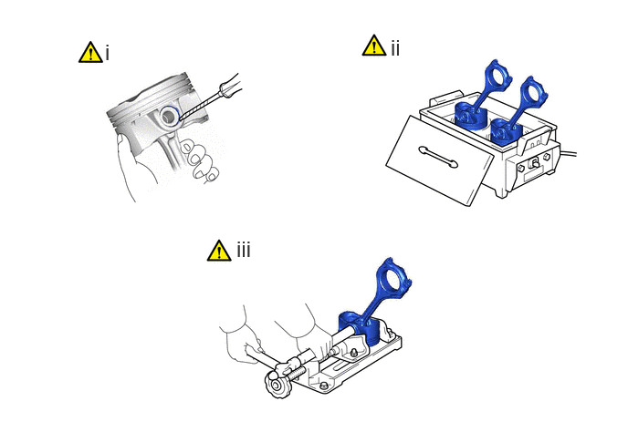
Using a screwdriver, pry out the 2 piston pin hole snap rings from the piston.
- HINT:
-
Tape the screwdriver tip before use.
Gradually heat each piston to between 80 and 90°C (176 and 194°F).
- CAUTION:
-
Be sure to wear protective gloves.
Using a brass bar and a hammer, lightly tap out the piston pin and remove the connecting rod.
- HINT:
- ·
The piston and piston pin are a matched set.
·Arrange the removed parts in such a way that they can be reinstalled to their original locations.
15708
13.REMOVE NO. 1 OIL NOZZLE SUB-ASSEMBLY
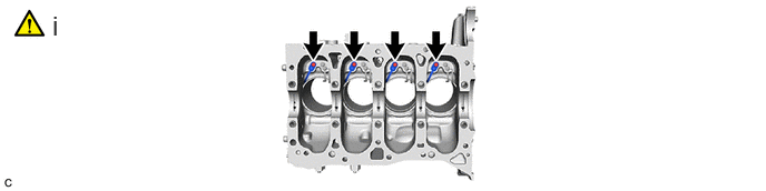
Using a 5 mm hexagon wrench, remove the 4 bolts and 4 No. 1 oil nozzle sub-assemblies from the cylinder block sub-assembly.
15709
14.REMOVE NO. 2 OIL NOZZLE SUB-ASSEMBLY
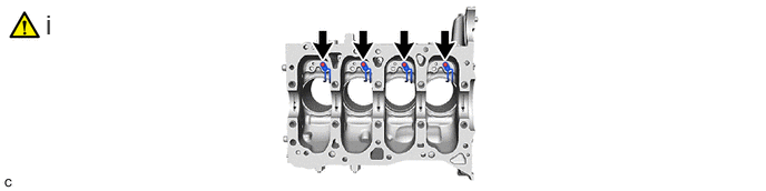
Using a 5 mm hexagon wrench, remove the 4 bolts and 4 No. 2 oil nozzle sub-assemblies from the cylinder block sub-assembly.
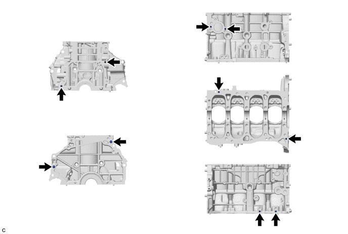
11115A
15.REMOVE RING PIN
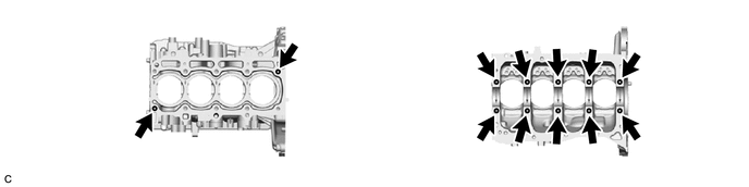
11434Q
16.REMOVE STRAIGHT PIN