M20F-FXS, M20G-FXS ENGINE MECHANICAL CYLINDER BLOCK INSPECTION
PROCEDURE

 1.INSPECT CYLINDER BLOCK FOR WARPAGE
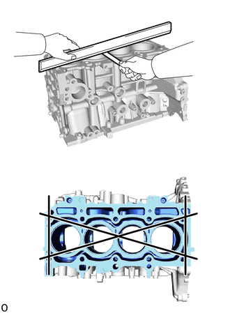
Using a precision straightedge and feeler gauge, check the surface which contacts the cylinder head gasket for warpage.
- Maximum Warpage:
0.05 mm (0.00197 in.)
- HINT:
-
If the warpage is more than the maximum, replace the cylinder block sub-assembly.
2.INSPECT CYLINDER BORE
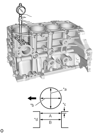
| *a | Thrust Direction |
| *b | Axial Direction |
| *c | 10 mm (0.394 in.) |
| *d | Center |

|
Front of Engine |
Using a cylinder gauge, measure the cylinder bore diameter at the positions (A) and (B) in the thrust and axial directions.
- Reference Diameter (New Parts):
80.500 to 80.513 mm (3.16929 to 3.16980 in.)
- Maximum Diameter:
80.633 mm (3.17452 in.)
- HINT:
-
If the average diameter of 4 positions is more than the maximum, replace the cylinder block sub-assembly.
3.INSPECT PISTON
- HINT:
-
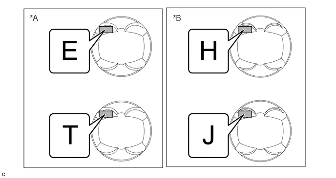
Type A and type B can be distinguished by the mark on the piston.
 0.51,0.188 3.469,3.594 2.958,3.406 3.552,0.167 6.51,3.573 2.958,3.406 0.635,0.281 1.01,0.521 0.375,0.24 12 false *A 3.688,0.281 4.063,0.521 0.375,0.24 12 false *B
*A Type A *B Type B
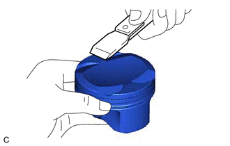
Using a gasket scraper, remove any carbon from the piston top.
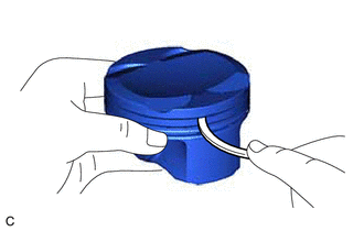
Using a groove cleaning tool or a broken ring, clean the piston ring grooves.
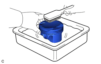
Using a brush and solvent, thoroughly clean the piston.
- NOTICE:
-
Do not use a wire brush.
Type A:
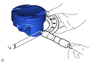
| *a | Distance |
Using a micrometer, measure the piston diameter at a right angle to the piston center line where the distance from the bottom of the piston is as specified.
- Distance:
10 mm (0.394 in.)
- Reference Piston Diameter (New Parts):
80.472 to 80.502 mm (3.16818 to 3.16936 in.)
- HINT:
-
If the diameter is less than the minimum, replace the piston and piston pin as a set.
Type B:
| *a | Distance |
Using a micrometer, measure the piston diameter at a right angle to the piston center line where the distance from the bottom of the piston is as specified.
- Distance:
8.5 mm (0.335 in.)
- Reference Piston Diameter (New Parts):
80.466 to 80.496 mm (3.16795 to 3.16913 in.)
- HINT:
-
If the diameter is less than the minimum, replace the piston and piston pin as a set.
4.INSPECT PISTON OIL CLEARANCE
- HINT:
-
Type A and type B can be distinguished by the mark on the piston.
-
0.51,0.188 3.469,3.594 2.958,3.406 3.552,0.167 6.51,3.573 2.958,3.406 0.635,0.281 1.01,0.521 0.375,0.24 12 false *A 3.688,0.281 4.063,0.521 0.375,0.24 12 false *B
*A Type A *B Type B
Type A:
Subtract the piston diameter measurement from the cylinder bore diameter measurement.
- Reference Oil Clearance (New Parts):
-0.002 to 0.041 mm (-0.0000787 to 0.00161 in.)
- Maximum Oil Clearance:
0.081 mm (0.00319 in.)
- HINT:
-
If the piston oil clearance is more than the maximum, replace all the pistons with piston pins. If necessary, replace the cylinder block sub-assembly.
Type B:
Subtract the piston diameter measurement from the cylinder bore diameter measurement.
- Reference Oil Clearance (New Parts):
0.004 to 0.047 mm (0.000157 to 0.00185 in.)
- Maximum Oil Clearance:
0.081 mm (0.00319 in.)
- HINT:
-
If the piston oil clearance is more than the maximum, replace all the pistons with piston pins. If necessary, replace the cylinder block sub-assembly.
5.INSPECT RING GROOVE CLEARANCE
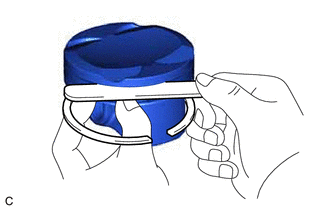
Using a feeler gauge, measure the clearance between a new piston ring set and the wall of the ring groove.
- Standard Ring Groove Clearance:
Item Specified Condition No. 1 compression ring 0.020 to 0.060 mm (0.00079 to 0.00236 in.) No. 2 compression ring 0.020 to 0.060 mm (0.00079 to 0.00236 in.) Oil ring 0.070 to 0.110 mm (0.00276 to 0.00433 in.)
- HINT:
-
If the groove clearance is not as specified, replace the piston and piston pin as a set.
6.INSPECT PISTON RING END GAP
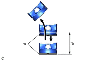
| *a | Piston Ring |
| *b | 70 mm |
Insert the piston ring into the cylinder bore.
Using a piston, push in the piston ring a little beyond the bottom of the ring travel, 70 mm (2.76 in.) from the top of the cylinder block sub-assembly.
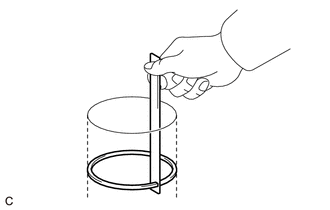
Using a feeler gauge, measure the end gap.
- Standard End Gap:
Item Specified Condition No. 1 compression ring 0.200 to 0.225 mm (0.00787 to 0.00886 in.) No. 2 compression ring 0.575 to 0.625 mm (0.02264 to 0.02461 in.) Oil ring 0.100 to 0.350 mm (0.00394 to 0.01378 in.)
- Maximum End Gap:
Item Specified Condition No. 1 compression ring 0.475 mm (0.0187 in.) No. 2 compression ring 0.875 mm (0.0344 in.) Oil ring 0.6 mm (0.0236 in.)
- HINT:
-
If the end gap is more than the maximum, replace the piston ring set. If the end gap is more than the maximum even with a new piston ring set, replace the cylinder block sub-assembly.
7.INSPECT PISTON PIN OIL CLEARANCE
- HINT:
-
When replacing the piston and piston pin with supply parts, there are a number of piston diameter sizes to choose from, but there is only one size of piston pin diameter.
Confirm each mark on the piston, piston pin and connecting rod.
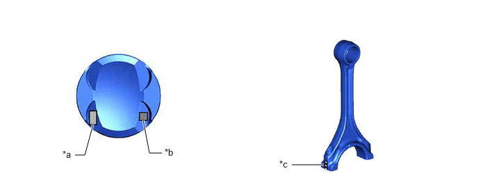
| *a | Front Mark | *b | Piston Pin Hole Inside Diameter Mark |
| *c | Connecting Rod Small End Bush Inside Diameter Mark | - | - |
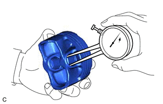
Using a caliper gauge, measure the inside diameter of the piston pin hole.
- Standard Piston Pin Hole Inside Diameter:
19.006 to 19.015 mm (0.74827 to 0.74862 in.)
Mark Specified Condition A 19.006 to 19.009 mm (0.74827 to 0.74838 in.) B 19.009 to 19.012 mm (0.74838 to 0.74850 in.) C 19.012 to 19.015 mm (0.74850 to 0.74862 in.)
- HINT:
-
If the diameter is not as specified, replace the piston and piston pin as a set.
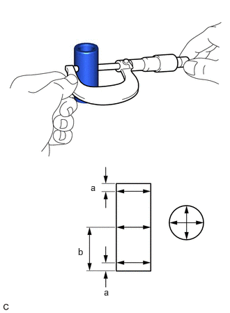
Using a micrometer, measure the piston pin diameter.
- Standard Piston Pin Diameter:
19.004 to 19.013 mm (0.74819 to 0.74854 in.)
Mark Specified Condition A 19.004 to 19.007 mm (0.74819 to 0.74831 in.) B 19.007 to 19.010 mm (0.74831 to 0.74842 in.) C 19.010 to 19.013 mm (0.74842 to 0.74854 in.)
- HINT:
-
If the diameter is not as specified, replace the piston and piston pin as a set.
- Measurement Position:
Measurement Position Piston Pin Position a 5.0 mm (0.197 in.) from side edge b 23.0 mm (0.906 in.) from side edge
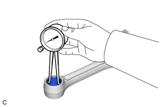
Using a caliper gauge, measure the inside diameter of the connecting rod small end bush.
- Standard Connecting Rod Small End Bush Inside Diameter:
19.012 to 19.021 mm (0.74850 to 0.74886 in.)
Mark Specified Condition A 19.012 to 19.015 mm (0.74850 to 0.74862 in.) B 19.015 to 19.018 mm (0.74862 to 0.74874 in.) C 19.018 to 19.021 mm (0.74874 to 0.74886 in.)
- HINT:
-
If the inside diameter is not as specified, replace the connecting rod sub-assembly.
Subtract the piston pin diameter measurement from the piston pin hole inside diameter measurement.
- Standard Oil Clearance:
-0.001 to 0.005 mm (-0.0000394 to 0.000197 in.)
- Maximum Oil Clearance:
0.015 mm (0.000591 in.)
- HINT:
-
If the oil clearance is more than the maximum, replace the piston and piston pin as a set.
Subtract the piston pin diameter measurement from the connecting rod small end bush inside diameter measurement.
- Standard Oil Clearance:
0.005 to 0.011 mm (0.000197 to 0.000433 in.)
- Maximum Oil Clearance:
0.021 mm (0.000827 in.)
- HINT:
-
If the oil clearance is more than the maximum, replace the connecting rod sub-assembly. If necessary, replace the connecting rod sub-assembly and piston pin as a set.
8.INSPECT CONNECTING ROD
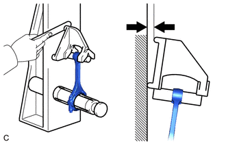
Using a connecting rod aligner and feeler gauge, check the connecting rod alignment.
Check for misalignment.
- Maximum Misalignment:
0.05 mm (0.00197 in.) per 100 mm (3.94 in.)
If the misalignment is more than the maximum, replace the connecting rod.
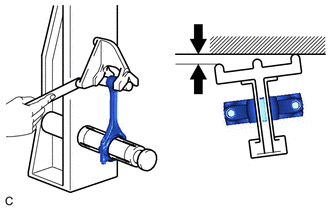
Check for twist.
- Maximum Twist:
0.15 mm (0.00591 in.) per 100 mm (3.94 in.)
If the twist is more than the maximum, replace the connecting rod.
13411
9.INSPECT CRANKSHAFT
Inspect for runout.
Clean the crank journal.
Place the crankshaft on V-blocks.
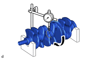
Using a dial indicator and V-blocks, measure the runout as shown in the illustration.
- Maximum Runout:
0.03 mm (0.00118 in.)
- HINT:
-
If the runout is more than the maximum, replace the crankshaft.
Inspect the main journals.
Using a micrometer, measure the diameter of each main journal.
- Standard Main Journal Diameter:
51.988 to 52.000 mm (2.04677 to 2.04724 in.)
- HINT:
-
If the diameter is not as specified, check the crankshaft oil clearance. If necessary, replace the crankshaft.
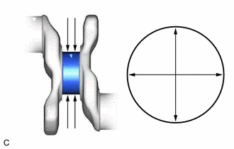
Check each main journal for taper and out-of-round as shown in the illustration.
- Maximum Taper and Out-of-round:
0.003 mm (0.000118 in.)
- HINT:
-
If the taper or out-of-round is more than the maximum, replace the crankshaft.
Inspect the crank pins.
Using a micrometer, measure the diameter of each crank pin.
- Standard Crank Pin Diameter:
47.992 to 48.000 mm (1.88945 to 1.88976 in.)
- HINT:
-
If the diameter is not as specified, check the connecting rod oil clearance. If necessary, replace the crankshaft.
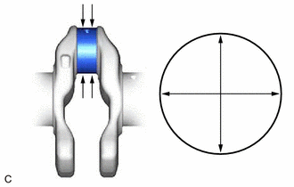
Inspect each crank pin for taper and out-of-round as shown in the illustration.
- Maximum Taper and Out-of-round:
0.003 mm (0.000118 in.)
- HINT:
-
If the taper or out-of-round is more than the maximum, replace the crankshaft.
10.INSPECT CRANKSHAFT OIL CLEARANCE
Install the crankshaft bearings.
Install the crankshaft thrust washers.
Place the crankshaft on the cylinder block sub-assembly.
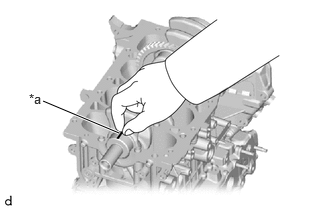
| *a | Plastigage |
Lay a strip of Plastigage across each journal.
Install the crankshaft bearing caps.
- NOTICE:
-
Do not turn the crankshaft.
Remove the crankshaft bearing caps.
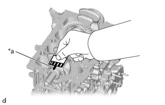
| *a | Plastigage |
Measure the Plastigage at its widest point.
- Standard Oil Clearance:
- for No. 3 journal:
0.024 to 0.040 mm (0.00094 to 0.00157 in.)
- except No. 3 journal:
0.012 to 0.028 mm (0.00047 to 0.00110 in.)
- Maximum Oil Clearance:
- for No. 3 journal:
0.040 mm (0.00157 in.)
- except No. 3 journal:
0.028 mm (0.00110 in.)
- NOTICE:
-
Remove the Plastigage completely after the measurement.
If the oil clearance is more than the maximum, replace the crankshaft bearing. If necessary, replace the crankshaft.
- HINT:
-
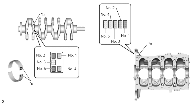
If replacing a crankshaft bearing, select a new one with the same number. If the number of the crankshaft bearing cannot be determined, calculate the correct crankshaft bearing number by adding together the numbers imprinted on the cylinder block sub-assembly and crankshaft. Then refer to the following table for the appropriate crankshaft bearing number. There are 4 sizes of standard bearings, marked "1", "2", "3", "4", "5" or "6" accordingly.
 1.208,0.927 1.448,0.521 true 0.813,2.49 1.125,2.969 1.125,2.969 0.792,2.75 true 5.104,1.969 5.375,1.635 false 4.563,1.219 4.563,1.021 false 3.844,1.219 3.844,1.021 false 4.198,1.417 4.198,1.031 false 4.063,0.74 4.021,0.531 false 4.417,0.74 4.24,0.271 false 2.427,2.042 2.24,2.042 true 2.417,2.531 2.229,2.531 true 1.885,2.521 1.698,2.521 true 1.896,2.281 1.708,2.281 true 1.885,2.052 1.698,2.052 true 5.427,1.521 5.74,1.677 0.313,0.156 10 false *a 1.5,0.448 1.813,0.604 0.313,0.156 10 false *b 1.083,2.979 1.396,3.135 0.313,0.156 10 false *c 2.49,1.938 2.885,2.135 0.396,0.198 10 false No. 1 1.323,1.938 1.719,2.135 0.396,0.198 10 false No. 2 1.344,2.188 1.74,2.385 0.396,0.198 10 false No. 3 2.469,2.438 2.865,2.635 0.396,0.198 10 false No. 4 1.354,2.427 1.75,2.625 0.396,0.198 10 false No. 5 3.688,1.24 4.083,1.438 0.396,0.198 10 false No. 5 4.063,1.427 4.458,1.625 0.396,0.198 10 false No. 3 3.865,0.198 4.26,0.396 0.396,0.198 10 false No. 2 3.677,0.438 4.073,0.635 0.396,0.198 10 false No. 4 4.427,1.219 4.823,1.417 0.396,0.198 10 false No. 1
*a Cylinder Block Number Mark (A) *b Crankshaft Number Mark (B) *c Diameter Mark - -
EXAMPLE
for No. 3 journal:
Cylinder block sub-assembly (A) "3" + Crankshaft (B) "4" = Total "7".
Select the crankshaft bearing marked "3".
except No. 3 journal:
Cylinder block sub-assembly (A) "3" + Crankshaft (B) "4" = Total "7".
Select the crankshaft bearing marked "5".
- Crankshaft Bearing Chart (for No. 3 journal):
(A) + (B) Use Crankshaft Bearing 0 to 2 1 3 to 5 2 6 to 8 3 9 to 11 4
- Crankshaft Bearing Chart (except No. 3 journal):
(A) + (B) Use Crankshaft Bearing 0 to 2 3 3 to 5 4 6 to 8 5 9 to 11 6
- Standard Cylinder Block Journal Inside Diameter (A):
Mark Specified Condition 0 56.000 to 56.003 mm (2.20472 to 2.20484 in.) 1 56.003 to 56.005 mm (2.20484 to 2.20492 in.) 2 56.005 to 56.007 mm (2.20492 to 2.20500 in.) 3 56.007 to 56.010 mm (2.20500 to 2.20511 in.) 4 56.010 to 56.012 mm (2.20511 to 2.20519 in.) 5 56.012 to 56.014 mm (2.20519 to 2.20527 in.) 6 56.014 to 56.016 mm (2.20527 to 2.20535 in.)
- Standard Crankshaft Main Journal Diameter (B):
Mark Specified Condition 0 51.998 to 52.000 mm (2.04716 to 2.04724 in.) 1 51.996 to 51.998 mm (2.04708 to 2.04716 in.) 2 51.994 to 51.996 mm (2.04700 to 2.04708 in.) 3 51.992 to 51.994 mm (2.04693 to 2.04700 in.) 4 51.990 to 51.992 mm (2.04685 to 2.04693 in.) 5 51.988 to 51.990 mm (2.04677 to 2.04685 in.)
- Standard Crankshaft Bearing Center Wall Thickness:
Mark Specified Condition 1 1.985 to 1.988 mm (0.07815 to 0.07827 in.) 2 1.988 to 1.991 mm (0.07827 to 0.07839 in.) 3 1.991 to 1.994 mm (0.07839 to 0.07850 in.) 4 1.994 to 1.997 mm (0.07850 to 0.07862 in.) 5 1.997 to 2.000 mm (0.07862 to 0.07874 in.) 6 2.000 to 2.003 mm (0.07874 to 0.07886 in.)
Perform the inspection for each journal.
11416
11.INSPECT CRANKSHAFT BEARING CAP SET BOLT
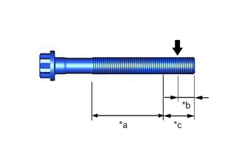
| *a | Measurement Area (B) |
| *b | 5.0 mm (0.197 in.) |
| *c | 10 mm (0.394 in.) |
|
|
Measurement Location (A) |
Using a vernier caliper, measure the outer diameter at position (A) shown in the illustration.
- Standard Diameter:
10.73 to 10.97 mm (0.422 to 0.432 in.)
Using a vernier caliper, measure the outer diameter within range (B) shown in the illustration at several locations.
- HINT:
- ·
Perform the measurement within range (B) at several locations.
·If the threads of the crankshaft bearing cap set bolt are damaged, replace the bolt with a new one.
Calculate the difference between the measurement at position (A) and position (B).
- Minimum Diameter:
The outer diameter difference is 0.3 mm (0.0118 in.)
- HINT:
- ·
Outer Diameter Difference = Position (A) Outer Diameter - Position (B) Outer Diameter (Smallest Value)
·If the outer diameter is below the minimum, the engine may be damaged.
Therefore, replace the crankshaft bearing cap set bolt with a new one.
13265
12.INSPECT CONNECTING ROD BOLT
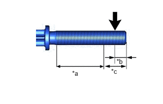
| *a | Measurement Area (B) |
| *b | 5.0 mm (0.197 in.) |
| *c | 10 mm (0.394 in.) |
|
|
Measurement Location (A) |
Using a vernier caliper, measure the outer diameter at position (A) shown in the illustration.
- Standard Diameter:
8.36 to 8.5 mm (0.329 to 0.335 in.)
Using a vernier caliper, measure the outer diameter within range (B) shown in the illustration at several locations.
- HINT:
- ·
Perform the measurement within range (B) at several locations.
·If the threads of the connecting rod bolt are damaged, replace the bolt with a new one.
Calculate the difference between the measurement at position (A) and position (B).
- Minimum Diameter:
The outer diameter difference is 0.05 mm (0.00197 in.)
- HINT:
- ·
Outer Diameter Difference = Position (A) Outer Diameter - Position (B) Outer Diameter (Smallest Value)
·If the outer diameter is below the minimum, the engine may be damaged.
Therefore, replace the connecting rod bolt with a new one.
15708
13.INSPECT NO. 1 OIL NOZZLE SUB-ASSEMBLY

| *a | Air |
Blow air into the (A) side, and check that air passes through (B) easily.
- HINT:
-
If the result is not as specified, replace the No. 1 oil nozzle sub-assembly.
15709
14.INSPECT NO. 2 OIL NOZZLE SUB-ASSEMBLY
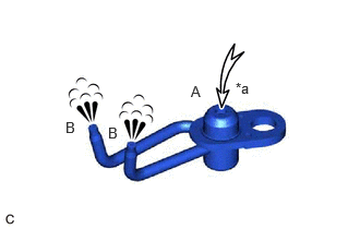
| *a | Air |
Blow air into the (A) side, and check that air passes through (B) easily.
- HINT:
-
If the result is not as specified, replace the No. 2 oil nozzle sub-assembly.