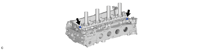
M20F-FXS, M20G-FXS ENGINE MECHANICAL CYLINDER HEAD DISASSEMBLY
CAUTION / NOTICE / HINT
The necessary procedures (adjustment, calibration, initialization or registration) that must be performed after parts are removed and installed, or replaced during cylinder head removal/installation are shown below.
| Replaced Part or Performed Procedure | Necessary Procedure | Effect/Inoperative Function when Necessary Procedure not Performed | Link |
|---|---|---|---|
| Replacement of cylinder head sub-assembly | Inspection after repair | ·
Poor idle, etc. ·
Engine start function, etc. |
( 202307,999999,_51,_144956,_0604911,RM100000002BWPD,) 202307,999999,_51,_144956,_0604911,RM100000002BWPD,)
|
CAUTION / NOTICE / HINT
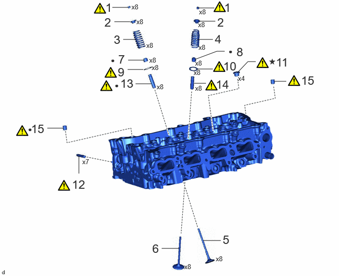
| Procedure | Part Name Code | 
|

|

|
|
|---|---|---|---|---|---|
| 1 | VALVE SPRING RETAINER LOCK | 13741A | (202307,999999,_51,_144958,_0604255,RM100000002BTSJ_01_0016,)
|
- | - |
| 2 | VALVE SPRING RETAINER | 13741B | - | - | - |
| 3 | INTAKE VALVE COMPRESSION SPRING | 13711M | - | - | - |
| 4 | EXHAUST VALVE COMPRESSION SPRING | 13715H | - | - | - |
| 5 | INTAKE VALVE | 13711 | - | - | - |
| 6 | EXHAUST VALVE | 13715 | - | - | - |
| 7 | INTAKE VALVE STEM OIL SEAL | 13711E | - | - | - |
| 8 | EXHAUST VALVE STEM OIL SEAL | 13715A | - | - | - |
| 9 | INTAKE VALVE SPRING SEAT | 13734A | (202307,999999,_51,_144958,_0604255,RM100000002BTSJ_01_0021,)
|
- | - |
| 10 | EXHAUST VALVE SPRING SEAT | 13734B | (202307,999999,_51,_144958,_0604255,RM100000002BTSJ_01_0015,)
|
- | - |
| 11 | NO. 1 STRAIGHT SCREW PLUG | 11117E | - | - | - |
| 12 | STUD BOLT | - | (202307,999999,_51,_144958,_0604255,RM100000002BTSJ_01_0013,)
|
- | - |
| 13 | INTAKE VALVE GUIDE BUSH | 11122 | (202307,999999,_51,_144958,_0604255,RM100000002BTSJ_01_0012,)
|
- | - |
| 14 | EXHAUST VALVE GUIDE BUSH | 11126 | (202307,999999,_51,_144958,_0604255,RM100000002BTSJ_01_0011,)
|
- | - |
| 15 | RING PIN | 11115A | (202307,999999,_51,_144958,_0604255,RM100000002BTSJ_01_0010,)
|
- | - |
| ● | Non-reusable part | ★ | Precoated part |
PROCEDURE

 13741A
1.REMOVE VALVE SPRING RETAINER LOCK
13741A
1.REMOVE VALVE SPRING RETAINER LOCK
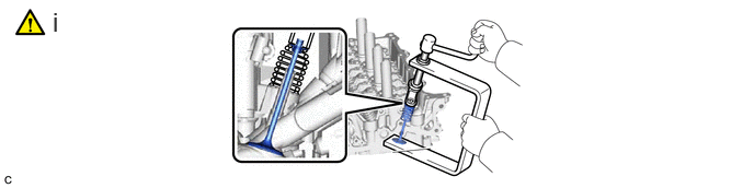
Using SST, compress each compression spring and remove the 16 valve spring retainer locks.
- SST
- 09202-70020 (09202-01010, 09202-01020)
09202-00021
13741B
2.REMOVE VALVE SPRING RETAINER
13711M
3.REMOVE INTAKE VALVE COMPRESSION SPRING (for Intake Side)
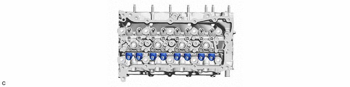
13715H
4.REMOVE EXHAUST VALVE COMPRESSION SPRING (for Exhaust Side)
Perform the same procedure as for the intake side.
13711
5.REMOVE INTAKE VALVE
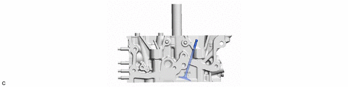
13715
6.REMOVE EXHAUST VALVE
Perform the same procedure as for the intake side.
13711E
7.REMOVE INTAKE VALVE STEM OIL SEAL (for Intake Side)

13715A
8.REMOVE EXHAUST VALVE STEM OIL SEAL (for Exhaust Side)
Perform the same procedure as for the intake side.
13734A
9.REMOVE INTAKE VALVE SPRING SEAT (for Intake Side)
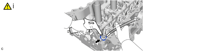
Using compressed air and a Magnet Hand, remove the 8 intake valve spring seats from the cylinder head sub-assembly by blowing air onto them.
13734B
10.REMOVE EXHAUST VALVE SPRING SEAT (for Exhaust Side)
Perform the same procedure as for the intake side.
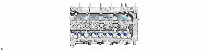
11117E
11.REMOVE NO. 1 STRAIGHT SCREW PLUG
|
|
|

Using a 6 mm straight hexagon wrench, remove the 4 No. 1 straight screw plugs from the cylinder head sub-assembly.
12.REMOVE STUD BOLT
|
|
|
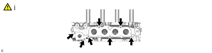
Using an E8 "TORX" socket wrench, remove the 7 stud bolts.
11122
13.REMOVE INTAKE VALVE GUIDE BUSH
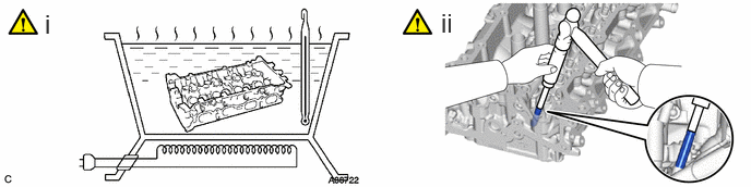
Heat the cylinder head sub-assembly to between 80 and 100°C (176 and 212°F).
Place the cylinder head sub-assembly on wooden blocks.
- CAUTION:
-
Be sure to wear protective gloves.
Using SST and a hammer, tap out the intake valve guide bush.
- SST
- 09201-01055
09950-70010 (09951-07100)
11126
14.REMOVE EXHAUST VALVE GUIDE BUSH
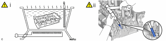
Heat the cylinder head sub-assembly to between 80 and 100°C (176 and 212°F).
Place the cylinder head sub-assembly on wooden blocks.
- CAUTION:
-
Be sure to wear protective gloves.
Using SST and a hammer, tap out the exhaust valve guide bush.
- SST
- 09201-01055
09950-70010 (09951-07100)
11115A
15.REMOVE RING PIN
|
|
|